
Page 413 - Adams and Stashak's Lameness in Horses, 7th Edition
P. 413
Diagnostic Imaging 379
VetBooks.ir
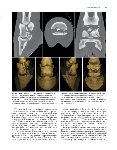
Figure 3.196. MPR and 3D rendering of a middle phalanx the position of the different fragments. The bottom row displays
fracture.CT images of the left hind pastern of a 5‐year‐old four different projections of three‐dimensional (3D) rendering.
Warmblood gelding with a complex, comminuted fracture of the The 3D rendering has the advantage to provide a similar
middle phalanx. The top row presents multiplanar reformatted visualization to what would be seen during surgery. The informa
images displayed in the sagittal (left), transverse (center), and tion about the internal configuration of the fracture is however
dorsal plane (right). This display provides the best assessment of lost in this display.
CT is also particularly convenient to image complex excellent visualization of the hoof wall. For this reason,
structures where several abnormalities might be present CT is the imaging technique of choice for surgical
12
concurrently such as in the foot 23,24,26 or the suspensory planning for resection of keratomas (Figure 4.58).
ligament origin. In addition to providing improved Keratomas have a typical heterogeneous hyperattenuat
15
assessment of the navicular bone when compared with ing appearance, and their connection with the hoof wall
radiographs, CT allows detection of lesions at ligamen can be well appreciated. CT can be used for guidance to
tous attachments such as the collateral ligaments of the mark the localization of the keratoma on the hoof wall,
distal interphalangeal (DIP) joint or the distal sesamoid in order to optimize the size and localization of the hoof
ean impair ligament, as well as assessment of the sub wall resection (Figure 4.59).
chondral bone, the hoof wall, and the soft tissue Joint assessment is another area where CT can be
including the tendons (Figure 3.198). quite useful. CT is excellent at assessing the subchondral
CT is also quite useful for assessment of the hoof and bone and is beneficial in recognizing and characterizing
related structures. Keratinized structures are difficult to subchondral resorptive lesions, for example, in the sagit
appreciate on MRI as they present a hypointense signal tal groove of the proximal aspect of the proximal pha
10
similar to the surrounding air, whereas on CT, the kera lanx, and other cyst‐like lesions (Figure 3.199). The
tin is hyperattenuating to the soft tissue, leading to classic radiographic findings of osteoarthritis, including