
Page 120 - Divyank Tyagi
P. 120
86 | ChapTER 3 The Basics of The ToolBox
are explicitly joined. This is where the Join Geometry tool comes into play. This tool creates
joins between floors, walls, ceilings, roofs, and slabs. A common use for this tool is in building
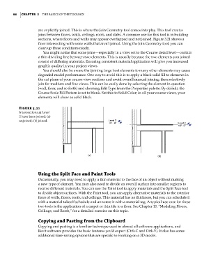
sections, where floors and walls may appear overlapped and not joined. Figure 3.21 shows a
floor intersecting with some walls that aren’t joined. Using the Join Geometry tool, you can
clean up these conditions nicely.
You might notice that some joins—especially in a view set to the Course detail level—contain
a thin dividing line between two elements. This is usually because the two elements you joined
consist of differing materials. Ensuring consistent material application will give you increased
graphic quality in your project views.
You should also be aware that joining large host elements to many other elements may cause
degraded model performance. One way to avoid this is to apply a black solid fill to elements in
the cut plane of your course view sections and avoid overall manual joining; then selectively
join for medium and fine views. This can be easily done by selecting the element in question
(wall, floor, and so forth) and choosing Edit Type from the Properties palette. By default, the
Course Scale Fill Pattern is set to blank. Set this to Solid Color; in all your course views, your
elements will show as solid black.
Figure 3.21
intersections at level
2 have been joined: (a)
unjoined; (b) joined.
(a) (b)
Using the Split Face and paint Tools
Occasionally, you may need to apply a thin material to the face of an object without making
a new type of element. You may also need to divide an overall surface into smaller regions to
receive different materials. You can use the Paint tool to apply materials and the Split Face tool
to divide object surfaces. With the Paint tool, you can apply alternative materials to the exterior
faces of walls, floors, roofs, and ceilings. This material has no thickness, but you can schedule it
with a material takeoff schedule and annotate it with a material tag. A typical use case for these
two tools is the application of a carpet or thin tile to a floor. See Chapter 13, “Modeling Floors,
Ceilings, and Roofs,” for a detailed exercise on this topic.
Copying and pasting from the Clipboard
Copying and pasting is a familiar technique used in almost all software applications, and
Revit software provides the basic features you’d expect (Ctrl+C and Ctrl+V). It also has some
additional time-saving options that are specific to working on a 3D model.
c03.indd 86 5/3/2014 10:31:02 AM