
Page 181 - Divyank Tyagi
P. 181
|
CreaTing CusTom annoTaTions 147
3. Select the arcs that create the circle and delete them.
4. On the Home tab of the Text panel, click the Label button. Position your cursor between
the two vertical reference planes and below the horizontal plane, and click to position the
start of the label.
5. In the Edit Label dialog box, select Sheet Number. Click the Add Parameter(s) To Label
button. In the Sample Value column, you can enter a value; the default is A101.
The label is placed and displays blue grips when selected. These let you change the
length of the label text field. The length is important because any value that is added (in
a project) that is longer than the length of this box will begin to wrap and could cause
undesirable results.
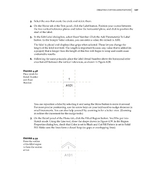
6. Following the same principle, place the label Detail Number above the horizontal refer-
ence but still between the vertical references, as shown in Figure 4.38.
Figure 4.38
place labels for
detail number
and sheet
number.
You can reposition a label by selecting it and using the Move button to move it around.
For more precise positioning, use the arrow keys on your keyboard to nudge elements in
small increments. You can also help yourself by zooming in for a better view. (Zooming
in refines the increment for the nudge tools.)
7. On the Detail panel of the Home tab, click the Filled Region button. You’ll be put into
Sketch mode. Using the Line tool, draw the shape shown in Figure 4.39. In the Region
Properties dialog box, check that Color is set to Black and Cut Fill Pattern is set to Solid
Fill. Make sure the lines form a closed loop (no gaps or overlapping lines).
Figure 4.39
draw the outline
of the filled region
to form the section
arrow.
c04.indd 147 5/3/2014 10:37:05 AM