
Page 368 - Divyank Tyagi
P. 368
334 | ChApter 9 ConCeptual Design anD Design analysis
3. Orbit the 3D view slightly, and then click Left or Right from the ViewCube. Start the
Reference + Spline tools again and choose Reference Plane : Center (Left/Right) from the
Options bar. Draw two more reference splines, one on either side of the centerline.
4. Your next step is to join the splines with horizontal reference lines. This will allow you to
establish some benchmarks for inserting the platform family you just created. For each of
the sets of horizontal reference lines you create, you’re going to insert another instance
of the adaptive component family. To add the reference lines, you’ll draw those in the
Left/Right plane to start. You want the reference lines to intersect both sets of points but
to extend past them on both ends. The length of the reference line will determine how
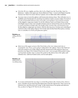
far the adaptive component can stretch. Start by drawing one at the base and extending it
past both ends of the spline (Figure 9.15). Do the same for the Front/Back plane, making
sure to remember to switch your placement plane.
Figure 9.15
adding reference
lines
5. Select one of the upper corners of the ViewCube so the view rotates back into an
axonometric view. Next, you’re going to add points to the splines. Choose the Point tool
and add a point to each of the splines near the intersections of the reference lines you
just drew; see Figure 9.16. It doesn’t have to be exact—once you get all the points in place
you’ll perform another step to connect the points to the intersection of the spline and
reference line. Add four hosted points, one for each spline.
Figure 9.16
adding points to
the reference lines
6. As we just mentioned, the next step is to attach the points to the reference lines. Select a
point, and then choose Host Point By Intersection from the Options bar. Then choose the
reference line, and the point will “jump” to the intersection of the spline and reference
line, as shown in Figure 9.17. Do this for all four points.
c09.indd 334 5/3/2014 11:01:05 AM