
Page 483 - Divyank Tyagi
P. 483
|
unDeRstanDing PHoto-RealistiC Visualization 449
2. Right-clicking the path will allow you to manipulate each of the series of views that you
just created. Right-click the nodes on the path and choose Go To View.
If your walkthrough path is not displayed, look in the Project Browser for the
Walkthrough category and locate the walkthrough view you just created. Right-click it
and select Show Camera from the context menu.
3. Double-click the walkthrough view in the Project Browser to open the view as you would
any of the other views.
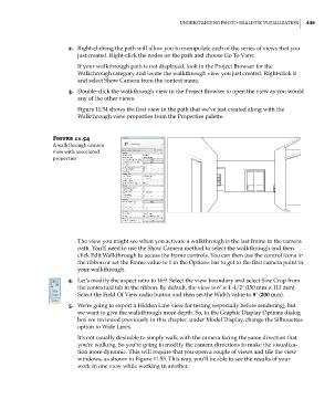
Figure 11.54 shows the first view in the path that we’ve just created along with the
Walkthrough view properties from the Properties palette.
Figure 11.54
a walkthrough camera
view with associated
properties
The view you might see when you activate a walkthrough is the last frame in the camera
path. You’ll need to use the Show Camera method to select the walkthrough and then
click Edit Walkthrough to access the frame controls. You can then use the control icons in
the ribbon or set the Frame value to 1 in the Options bar to get to the first camera point in
your walkthrough.
4. Let’s modify the aspect ratio to 16:9. Select the view boundary and select Size Crop from
the contextual tab in the ribbon. By default, the view is 6ʺ × 4 -1/2ʺ (150 mm × 113 mm).
Select the Field Of View radio button and then set the Width value to 8ʺ (200 mm).
5. We’re going to export a Hidden Line view for testing (especially before rendering), but
we want to give the walkthrough more depth. So, in the Graphic Display Options dialog
box we reviewed previously in this chapter, under Model Display, change the Silhouettes
option to Wide Lines.
It’s not usually desirable to simply walk with the camera facing the same direction that
you’re walking. So you’re going to modify the camera directions to make the visualiza-
tion more dynamic. This will require that you open a couple of views and tile the view
windows, as shown in Figure 11.55. This way, you’ll be able to see the results of your
work in one view while working in another.
c11.indd 449 5/3/2014 11:07:16 AM