
Page 235 - Maxwell House
P. 235
Chapter 5 215
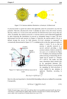
a) b)
Figure 5.2.6 Antenna radiation illustration: a) Isotropic, b) Directional
Its physical model is a point-size radiator that apparently cannot be connected to any real size
generator. Therefore, all physically available antennas are more or less directional, meaning
that they radiate in or receive from some particular far field directions more energy than any
others. Eventually, the radiation properties or antenna patterns can be illustrated graphically
by plots displaying the distribution of received or transmitted energy in space. We have
demonstrated several such patterns in Chapter 4. Typically, the antenna pattern (, ) is
8
defined through the electric far field intensity (, , ) calculated or measured (as
schematically demonstrated in Figure 5.2.7 ) at multiple points on the blue spherical surface of
9
radius = . To do so, the test
antenna is typically mounted on a
Elevation
Test Rotation special pedestal providing a high
Antenna accuracy antenna rotations around the
Azimuth
Rotation two axes as it is indicated in Figure
Probe 5.2.7. Evidently, the stationary far field
probe receiving or transmitting the test
signal can be located at a distance
2
Far-Field of > /λ. The reader can find
Sphere more information about antenna tests
in the specialized literature [35].
Recall that in Chapter 4 we proved that
the expanding far field wavefront of
Figure 5.2.7 Spherical far-field test setup (not in waves emitted by any antennas is
scale) spherical. Therefore, according to
(4.66)
−
(, , ) = (, ) (5.30)
0
Here is the peak magnitude of electrical field depending on the power radiated by an antenna.
0
Consequently,
(, ) = lim�(, , )� (5.31)
0
→∞
8 Public Domain Image, source with some editing: http://ww2.nearfield.com/amta/Amta98_gh_df.htm
9 Not drown to scale because the sphere radius must be in far-field zone of antenna meaning that the
sphere radius much exceed any of antenna dimensions (see (5.29))