
Page 236 - Maxwell House
P. 236
216 ANTENNA BASICS
The constant phase factor − is omitted as nonessential. The factor is defined in such way
0
that at the peak |( , )| = 1 where , are the angular coordinates of the emitted field
0
0
0
0
maxima. In practice, the far field vector of the electric field may comprise more than one
component. If so, the measurements must be repeated for each of them and included in the
database of antenna test. There are numerous variants of antenna pattern |(, )|
representation.
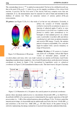
3D pattern (see Figure 5.2.8a, b) is the works of art but not very informative. Evidently, it
defines the variation of E-fields (typically)
emitted or received by an antenna in space as a
function of spherical angles and at some
fixed distance in far field area. A pattern can be
plotted in relative units (normalized to the
boresight or total radiated power) on a linear
scale or preferable in decibels (dB) and allows
visualizing how and where an antenna transmits
and receives EM energy. Usually, the antenna
pattern is frequency dependable. If so, each plot
might be marked with a specific frequency or
a) b) range of frequencies.
Multiple 2D slices of 3D pattern in Cardinal
Figure 5.2.8 Illustration of 3D pattern cuts such as E- or H-plane, vertical (like Figure
5.2.8b) or horizontal planes, azimuth or
elevation planes and many other cuts might represent an antenna performance much better
depending on pattern shape complexity. Any of such 2D pattern slices can be drawn in Cartesian
coordinates as shown in Figure 5.2.8c (normalized in logarithmic scale) or cylindrical
coordinates in Figure 5.2.8d (normalized in linear scale). The main beam is the part of antenna
[dB]
- 3 dB Level
c)
Main
Beam
Sidelobes Sidelobes
d)
Figure 5.2.8 Illustration of c) 2D pattern slice and d) pattern in cylindrical coordinates
pattern where maximum emitted power is concentrated. Beamwidth (BW ) or Half-Power-
−3
BeamWidth (HPBW) of an antenna pattern is determined by the angular separation of the half-
power points (i.e. -3 dB) of the radiated pattern as shown in Figure 5.2.8c. To better control the
antenna pattern shape, the beamwidth may be additionally specified at the level -10 dB (BW −10 )
and sometimes at the level like -20dB (BW −20 ). All other beams of the pattern belong to
sidelobes representing the energy radiated in or received from typically undesired directions.