
Page 238 - Maxwell House
P. 238
218 ANTENNA BASICS
Additional ripples in the measured antenna pattern can appear due to specular ground
reflections and reflections from the surrounding objects in the test range (like elements of
pedestal and probe (see Figure 5.2.7)). They can also be caused by antenna-probe polarization
and position misalignment, test system receiver nonlinearity, phase variations and additional
reflections in cables connecting the probe and antenna to test equipment, temperature
amplitude, and phase drift during the measurement, noise level in data collection system, and
many others. The complete calibration procedure can minimize most of these measurement
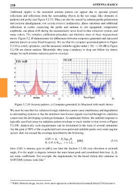
errors. Figure 5.2.10 demonstrates the differences between computers generated and measured
antenna pattern at some fixed frequency. We see that the computer generated pattern in Figure
5.2.10 is overly optimistic, and the measured sidelobe ripples under (-30) – (-40) dB in Figure
5.2.10b are almost random. Meanwhile, they keep a tendency to drop and follow the almost
unique for each antenna radiation pattern envelope.
a) b)
Figure 5.2.10 Antenna pattern: a) Computer generated, b) Measured with musk shown
We must be sure that the radiation through sidelobes cannot cause interference and degradation
to surrounding systems or that the dominant interference signals received through the sidelobes
cannot ruin the developing system performance. As mentioned before, the sidelobe response is
typically specified using the radiation pattern envelope or mask similar to that shown in Figure
5.2.10b. Analytically such requirements can be formulated in the form of several statements
like the gain of 90% of the co-polarized and cross-polarized sidelobe peaks over some angular
sectors shall not exceed the envelope described by the following:
() = − log ,
10 (5.34)
[dBi]
≤ ≤ +1 , = 1,2, …
Here () is antenna gain in [dBi] (see later the Section 5.2.10) over elevation or azimuth
angle, is the angle in degrees between the main beam peak and considered direction, ,
are some coefficients. For example, the requirements for the based station dish antennas in
SATCOM systems looks like
11
11 Public Domain Image, source: www.amos-spacecom.com/resources/resourceLibrary/2/3/documents