
Page 237 - Maxwell House
P. 237
Chapter 5 217
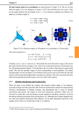
3D and contour plots in uv-coordinates are demonstrated in Figure 5.2.9. The set of three
10
direction angles , , are displayed in Figure 5.2.9a and called the direction angles. They
are the angles between the unit length vector = 1 in Cartesian coordinate and related to the
spherical coordinate angles as
= cos = sin ∙ cos
= cos = sin ∙ sin� (5.32)
= cos = cos
Figure 5.2.9 a) Direction angles, b) 3D pattern in uv-coordinates, c) Contour plot
The inverse transform is
−1
⁄
= tan ( ) if > 0
= − tan ( ) if < 0� (5.33)
−1
⁄
−1 2 2
= = sin (√ + )
Evidently, || ≤ 1, || ≤ 1 and || ≤ 1. Practically, the most informative image is 2D contour
plot with color bar shown in Figure 5.2.9c. Each curve on this plot represents a horizontal slice
of a 3D antenna pattern in Figure 5.2.9b and shows the set of lines connecting the equipotential
points. The color bar specifies ranges of colors corresponding to each magnitude. The central
red-green-blue oval area in Figure 5.2.9c belongs to the antenna main beam while the blue side
regions with local maxima (lighter blue) correspond to sidelobes. The white areas between lobes
where the magnitude practically drops to zero are called “null” regions.
5.2.7 Sidelobes Specification and Grating Lobes
There are many causes behind the complex and irregular pattern shape of real antennas,
especially of large ones like a parabolic dish. Some are mechanical by nature like manufacturing
tolerance, misalignment of antenna elements, and deformation due to stress in antenna
construction and gravity, the impact of wind and temperature variations. Other ones are
electrical by nature like errors in antenna element magnitude and phase excitation, deviation
the antenna material parameters from specifications, etc. Although most of these imperfections
are small and randomly distributed, their influence can be quite substantial especially in the
angular sectors where we should expect little to no radiation.
10 Public Domain Image, source: https://en.wikipedia.org/wiki/Direction_cosine