
Page 239 - Maxwell House
P. 239
Chapter 5 219
() = 29 − 25 log 10 , 1° ≤ ≤ 20°
() = −3.5, 20° < ≤ 26.3°
() = 32 − 25 log 10 , 26.3° < ≤ 48°
() = −10, 48° <
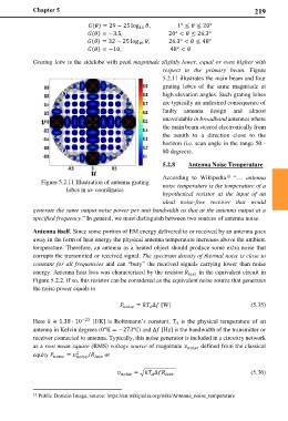
Grating lobe is the sidelobe with peak magnitude slightly lower, equal or even higher with
respect to the primary beam. Figure
5.2.11 illustrates the main beam and four
grating lobes of the same magnitude at
high elevation angles. Such grating lobes
are typically an undesired consequence of
faulty antenna design and almost
unavoidable in broadband antennas where
the main beam steered electronically from
the zenith to a direction close to the
horizon (i.e. scan angle in the range 50 -
80 degrees).
5.2.8 Antenna Noise Temperature
12
According to Wikipedia “… antenna
Figure 5.2.11 Illustration of antenna grating noise temperature is the temperature of a
lobes in uv-coordinates
hypothetical resistor at the input of an
ideal noise-free receiver that would
generate the same output noise power per unit bandwidth as that at the antenna output at a
specified frequency.” In general, we must distinguish between two sources of antenna noise.
Antenna itself. Since some portion of EM energy delivered to or received by an antenna goes
away in the form of heat energy the physical antenna temperature increases above the ambient
temperature. Therefore, an antenna as a heated object should produce some extra noise that
corrupts the transmitted or received signal. The spectrum density of thermal noise is close to
constant for all frequencies and can “bury” the received signals carrying lower than noise
energy. Antenna heat loss was characterized by the resistor in the equivalent circuit in
Figure 5.2.2. If so, this resistor can be considered as the equivalent noise source that generates
the noise power equals to
= ∆ [W] (5.35)
−23 [J/K] is Boltzmann’s constant, is the physical temperature of an
Here ≅ 1.38 ⋅ 10
antenna in Kelvin degrees (0°K = −273℃) and ∆ [Hz] is the bandwidth of the transmitter or
receiver connected to antenna. Typically, this noise generator is included in a circuitry network
as a root mean square (RMS) voltage source of magnitude defined from the classical
2 or
equity = /
= � ∆ (5.36)
12 Public Domain Image, source: https://en.wikipedia.org/wiki/Antenna_noise_temperature