
Page 305 - Maxwell House
P. 305
FEED LINE BASICS 285
Such choice diminishes the field radius and thus the possible interferences between adjacent
lines as well radiation loss, reduces weight and production cost, improves PCB packaging. But,
in fact, the lesser conductive surface at diminutive wavelengths means the relatively greater
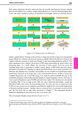
Figure 6.2.2 Stripline and vias illustration
electric current density flowing on the surfaces of strips and ground screens and consequently
greater Ohmic loss. Besides, the dielectric presence slightly reduces the difference between the
complex dielectric constant of metal (see Chapter 2) and surrounding dielectric medium. This
rarely mentioned effect enlarges the portion of EM energy penetrating the metal surface and
dissipating there. As a result, Ohmic loss increases to some extent. And even more, the
shrinking field radius is equivalent to higher volume density of EM fields and extra energy
absorption in the dielectric substrate. It is quite typical that Ohmic loss in strips dominates over
dielectric and radiation loss. Certainly, the striplines are not suitable for long-distance energy
transmission. But look on the bright side of the miniaturization process. In spite of larger loss
at higher frequencies, the overall RF energy loss might be quite acceptable because of the
substantial shrinking of interconnecting line length at a higher frequency. In fact, such type of
lines is used at frequencies up to 30 GHz and sometimes higher. The striplines are not capable
of handling EM waves of high power. The two most important phenomena, except the
fabrication faults, may restrict the transmitting power. Excessive increase in temperature due
to EM average energy loss in conductors and dielectric might lead to irreversible degradation
of dielectric and line structure. Another effect is extremely high concentration electrical fields
near the thin traces due to edge effect described in Chapter 3. The subsequent electrical
breakdown depending on the peak power may even cause a fire.
The most popular stripline design shown in Figure 6.2.2 is:
4
4 Public Domain Image, source with some editing: https://en.wikipedia.org/wiki/Via_fence and
http://www.qsl.net/va3iul/Microstrip_Stripline_CPW_Design/Microstrip_Stripline_and_CPW_Design.p
df