
Page 302 - Maxwell House
P. 302
282 Chapter 6
different lines like stripline and coaxial cable, waveguides of different shape or mode structure,
etc.
6.2 OPEN LINES
6.2.1 Open line Definition
Evidently, any line including the open one should transport EM energy with losses as low as
possible. If so, the impact of any material objects (buildings, people, supporting structures, etc.)
nearby should be minimized, i.e. the propagating EM energy must be concentrated in the line
vicinity. Traditionally, the degree of “openness or concentration” is measured by the integral
parameter called the field aperture or field diameter . Let us imagine that some open line like
shown in Figure 6.2.1 is devoided of shielding screen and placed as a whole inside some virtual
and oriented longitudinally cylinder of finite diameter. Then numerically or by measurements,
we could estimate how much transmitting energy accumulated in transverse extend inside and
outside this cylinder. Common requirement is that more than 90% of all carried energy should
be contained inside cylinder with diameter . The field diameter typically measured as the
portions of wavelength said (0.9) = 0.1. Evidently, the feeds with smaller less radiate,
better withstands the damaging impact of environment, less susceptible to influence of
interfering signals, and can be mounted more close to each other. It is important to point out
that any open line of finite length even lossless might radiate at the sport of its connection to
generator or load. Meanwhile, any open line of any length with non-zero dielectric and/or
Ohmic loss radiates more or less continuously like an antenna of traveling wave (see Chapter
5). Figures 6.2.1 and 6.2.2 illustrate some variety of open transmission lines. This list is non-
exhaustive but probably includes the leading part of well-tested and practically used lines.
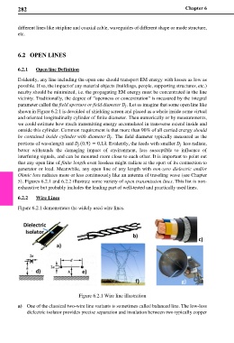
6.2.2 Wire Lines
Figure 6.2.1 demonstrates the widely used wire lines.
Figure 6.2.1 Wire line illustration
a) One of the classical two-wire line variants is sometimes called balanced line. The low-loss
dielectric isolator provides precise separation and insulation between two typically copper