
Page 312 - Maxwell House
P. 312
292 Chapter 6
2. From (6.13) follows that the refracted EM wave becomes trapped surface wave “glued”
to the boundary surface. Its intensity exponentially decays (evanescent) along the z-
direction. It is evident from the other equity in (6.11) that the concertation EM energy near
the boundary surface grows as the ratio and incident angle rise.
⁄
1
2
1
3. The propagation constant (see (6.13)) of EM waves moving parallel to the x-axis above (z
> 0) and below (z < 0) boundary are the same and equal to sin . Therefore, the surface
1
1
wave is a united EM field pattern or wave mode.
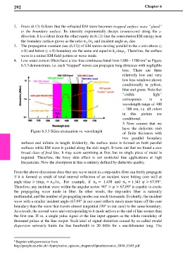
4. Low water content fibers have a low-loss continuous band from 1200 – 1700 nm as Figure
6
6.3.3 demonstrates, i.e. such “trapped” waves can propagate long distances with negligible
loss. There are three
relatively low and very
low loss windows shown
conditionally in yellow,
blue and green. Note that
"visible light"
corresponds to a
wavelength range of 400
– 700 nm, i.e. all colors
in this picture are
conditional.
5. Now assume that we
have the dielectric stub
Figure 6.3.3 Silica attenuation vs. wavelength of finite thickness with
two parallel boundary
surfaces and infinite in length. Evidently, the surface wave is formed on both parallel
surfaces while EM wave is guided along the stab length. It turns out that we found a new
broad class of feed line. It may seem surprising at first, but no single piece of metal is
required. Therefore, the lossy skin effect is not restricted line applications at high
frequencies. Now the absorption in line is entirely defined by dielectric quality.
From the above discussion clear that any wave mode in a step-index fiber can freely propagate
if it is formed as result of total internal reflection of an incident wave hitting core wall at
angle sin > sin = ⁄ . For example, if = 1.458 and = 1.343 > 67.09°.
2
1
2
1
Therefore, any incident wave within the angular sector 90° > > 67.09° is capable to excite
the propagating wave mode in fiber. In other words, the step-index fiber is naturally
multimodal, and the number of propagating modes can reach thousands. Evidently, the incident
wave with a smaller incident angle (67.09° in our case) reflects much more times off the core
boundary than the wave that travels almost tangential (90° in our case) to the same boundary.
As a result, the second wave and corresponding to it mode arrives at the end of line sooner than
the first one. If so, a single pulse signal at the line input appears as the whole roundelay of
thousand pulses at the line output. Such kind of signal distortion caused by so-called modal
dispersion seriously limits the line bandwidth to 20 MHz for a one-kilometer long. The
6 Reprint with permission from
http://people.ee.ethz.ch/~fyuriy/oe/oe_optcom_chapters/Optoelectronics_2010_Ch03.pdf