
Page 316 - Maxwell House
P. 316
296 Chapter 6
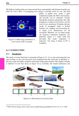
The fields in cladding stabs are evanescent and decay exponentially with distance from the core
while the “lion’s share” of propagating wave energy is confined within the core. The field
pattern of guided wave modes is quite
complicated, mainly TE, TM or their mixture,
and typically can be estimated correctly
through the numerical simulations only. The
propagation constant of each mode is also the
result of such simulations. Evidently, the total
energy of propagated modes is divided
between core, cladding, and surrounding air,
as Figure 6.3.8 demonstrates for rib
waveguide. Therefore, we can expect modal
and frequency (chromatic) dispersion. The
preferable regime is a single mode that
Figure 6.3.8 EM energy distribution in eliminates the modal component of
10
cross-section of rib waveguide dispersion. The image in Figure 6.3.8 is
exemplary.
6.4 CLOSED LINES
6.4.1 Introduction
The family of closed feed lines is presented in Figure 6.4.1. Let us start mentioning that any
open feed line we have just discussed can be transferred into the closed one by shielding, i.e.
placing it inside the highly conductive metal tube of the proper diameter. The simplest example
is shielded two-wire line shown in Figure 6.4.1a. Evidently, the outside interference and
Figure 6.4.1 Illustration of closed feed lines
10 Public Domain Image, source: https://www.osapublishing.org/oe/fulltext.cfm?uri=oe-18-21-21981