
Page 443 - Maxwell House
P. 443
MORE COMPLICATED ELEMENTS OF FEED LINES 423
Now assume the line is a quarter wavelength section meaning that = /2 when = Λ /4
14
0
0
and Λ is the wavelength at the central operation frequency . Since tan () → ∞ as →
0
0
/2, ≪ tan () and ≪ tan (). Therefore,
2
Λ 0 /4 = (8.14)
Relative Admittance Ideal Inverter
G
B
a) b)
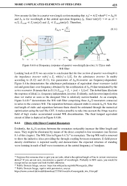
Figure 8.4.6 a) Frequency response of quarter-wavelength inverter, b) Three stub
WR filter
Looking back at (8.9) we can come to conclusion that the line section of quarter wavelength is
the impedance inverter with = while = 1/ for the admittance inverter. In reality
according to (8.12) and (8.13), this parameters of Λ /4-inverter are frequency-dependent.
0
Figure 8.4.6a demonstrates the admittance performance of equivalent shunt resonator (solid
red and green line) over frequency obtained by the combination of Λ /4-line terminated by the
0
series resonator. It means that in (8.13) = + ℒ + 1/. The dotted lines illustrate
the response of ideal, i.e. frequency independent, inverter. Evidently, such invertor imperfection
does not matter as soon as the designed filter is relatively narrow-banded. As an example,
Figure 8.4.6b demonstrates the WR stub filter comprising three Λ /2-resonators connected
15
0
in series to the common WR. The separation between adjacent stubs is around Λ /4. Note that
0
real length of stubs and separation between them should be estimated through the numerical
optimization using the tool like CST. It makes possible to take into account the fringe reactive
field of high modes accumulated around WR discontinuities. The final lumped equivalent
circuit of filter is depicted in Figure 8.4.6b.
8.4.6 Filters with Direct-Coupled Resonators
Evidently, the Λ /4-sections between the resonators noticeably increase the filter length and
0
mass. They might be eliminated by means of the direct-coupled in-line resonators (see Section
8.1 of this chapter). The WR filter in Figure 8.4.7a is exemplary. The top WR wall is removed
16
to show the inductive irises providing the through coupling between resonators. E-field power
density distribution is depicted nearby and demonstrates the expected structure of standing
wave forming in each of half-wave resonators at the central frequency of bandpass.
14 Suppose that someone tries to quiz you and asks, what is the optimal length of line in current microwave
device? If you are not sure, recommend a quarter of wavelength. Probably in 80% cases, you would be
recognized as an expert and look foolish otherwise.
15 Public Domain Image, source: https://en.wikipedia.org/wiki/Waveguide_filter
16 Public Domain Image, reprint with permission, source:
https://www.comsol.de/model/download/333961/models.rf.waveguide_iris_filter.pdf