Page 445 - Maxwell House
P. 445
MORE COMPLICATED ELEMENTS OF FEED LINES                                 425


                                                                     17
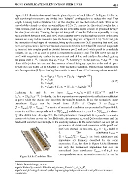
            Figure 8.4.8 illustrates two most favorite planar layouts of such filters . In Figure 8.4.8b the
            half-wavelength resonators are folded into  “hairpin” configuration to reduce the total filter
            length. Looking back at Section 8.2.3 of this chapter, we see that each of such filters is the
            cascaded directional couplers shown in Figure 8.2.2a. To convert the directional coupler into a
            filter element, port 2 and 3 of the coupler are not terminated (open-circuit) or grounded through
            the vias (short-circuit). Thereby, the injected into port1 of coupler EM wave repeatedly moving
            back and forth between port2 and port3 over a quarter-wavelength coupling section in the same
            manner as in any in-line resonator (see the bouncing diagram in Figure 8.1.1c). To investigate
            the properties of such type of resonator, bring up the expression (8.5) assuming that port2 and
            port3 are open-circuit. We know from discussion in Section 8.2.3 that EM wave of magnitude
              inserted into coupler port1 is divided between port2 and port3 while port4 is completely
             1
            isolated, i.e.  = 0 as soon as port4 is connected to dummy load. The EM wave passing in
                       4
            port2 with magnitude   reaches the open-circuit end of line and totally reflects back getting
                               2
                         −              −                       − . This
            the phase shift   . It means that  =    . Seemingly, in the port3  =
                                                                         3
                                              2
                                          2
                                                                              3
            phase shift  takes into account the presence of small fringing capacitor at the end of open-
            circuit line (see Table 7.1 in Chapter 7) with negligible radiation. Putting these relationships
            into the expression (8.5) and turning from matrix to usual form of the linear equations we obtain
                                =   +   = (  +   )  −
                                                    21 2
                                            31 3
                                     21 2
                                1
                                                           31 3
                                                                   ⎫
                                  =                                       (8.15)
                                2
                                     21 1
                                =
                                3    31 1                          ⎬
                                =   +   = (  +   )  − ⎭
                                4    31 2   21 3    31 2   21 3
            Excluding       and       we  have     =   = ( 21  +  ) −    and  =
                                                                   2
                                                                        2
                                                           ⁄
                                  3
                                                             1
                                                                       31
                                                          1
                        2
              ⁄
              = 2    − . Evidently, the first expression corresponds to the reflection coefficient
             4
                1
                     21 31
            in port1  while the second one describes the transfer  function. If  so, the normalized input
            impedance       can be   found   from (3.89) of Chapter 3 as      =
            �1 +   � �1 − �   �. The results of numerical simulation are presented in Figure 8.4.8c
            where the red line corresponds to  = ℜ�  � and the reactive part  = ℑ(  ) is shown

            by blue dotted line. As expected, the both parameters corresponds to  a  parallel resonator
            connected in shunt across the line. Evidently, the resonator external Q-factor increases and the
            bandwidth constricts accordingly as the coupling reduces. In the same manner, we can get the
                                            parameters of distributed resonators while port2 and
                                            port3 are shorted. In this case,   2,3  = −  and  =
                                                                              2,3
                                            0.           The           admittance    =
                                            �1 +   � �1 − �   �, i.e. both admittance and
                                            impedance are formally described by the same
                                            expression. If so, the plots in Figure 8.4.8c illustrates
                                            not only the  normalized impedance but also the
                                            normalized  input admittance     =  +   that
                                            corresponds to a series resonator connected across the
                Figure 8.4.9a Combline filter
            17  Public Domain Image, source:
            http://wikivisually.com/wiki/Distributed_element_filter/wiki_ph_id_45,
            http://www.lpkf.cn/applications/rapid-pcb-prototyping/design-articles/microstrip-filter-and-coupler-
            circuits.htm

