
Page 449 - Maxwell House
P. 449
MORE COMPLICATED ELEMENTS OF FEED LINES 429
means that the section of cutoff WR is a storage of mostly magnetic energy ( > ) and
thus may play the role of inductor. Evidently, such section can be converted into a shunt
resonance contour by putting inside a capacitive element, for example, capacitive post of
suitable sizes to reach the energy balance = at the desired resonance frequency as
Figure 8.4.12 depicts. Unluckily, the described resonance occurs in the volume that is much
smaller than the wavelength. In turn, it means the high concentration of EM energy in minor
volume and excessive conductivity current density on WR wall and capacitive element surfaces
at frequencies around the resonance. As a result, the evanescent resonators might have relatively
low unloaded Q-factor in comparison with classical in-line resonators, for example, but
certainly higher than the resonance iris or post could deliver. If it is true, why do we really need
them if they cannot rival with contemporary rectangular and circular waveguide cavity filters?
The main advantage of evanescent filters is their wideband rejection of spurious and harmonic
signals, sharp selectivity, compact size and low weight that is the critical issue for satellite and
mobile application.
One of the possible evanescent filter schematics is demonstrated in Figure 8.4.12a [20] . The
24
capacitive elements of cubical shape (blue dices) are symmetrically located on the upper and
lower walls of WR. Their structure reminds the section of WR with double ridges (WRD in
Figure 6.4.6 of Chapter 6). That is why they are sometimes called Evanescent Mode Ridge
Waveguide Filters. The regular input and output WRs of standard dimension /2 < < and
≅ /2 are connected to the section of cutoff WR with diminished sizes such as < /2.
The practical choice of and depends on how far from passband we desire to extend
the filter spurious-free stopband. Evidently, the reduction in sizes suppresses high mode
excitation and propagation as the frequency goes up but it certainly damages the passband
performance increasing the dissipation.
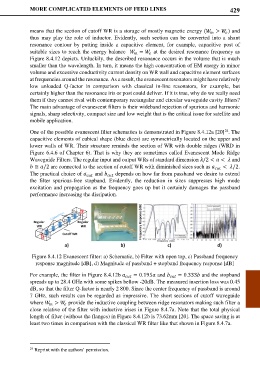
Figure 8.4.12 Evanescent filter: a) Schematic, b) Filter with open top, c) Passband frequency
response magnitude [dB], d) Magnitude of passband + stopband frequency response [dB]
For example, the filter in Figure 8.4.12b = 0.195 and = 0.333 and the stopband
spreads up to 28.4 GHz with some spikes bellow -20dB. The measured insertion loss was 0.45
dB, so that the filter Q-factor is nearly 2 800. Since the center frequency of passband is around
7 GHz, such results can be regarded as impressive. The short sections of cutoff waveguide
where > provide the inductive coupling between ridge resonators making such filter a
close relative of the filter with inductive irises in Figure 8.4.7a. Note that the total physical
length of filter (without the flanges) in Figure 8.4.12b is 73.62mm [20]. The space saving is at
least two times in comparison with the classical WR filter like that shown in Figure 8.4.7a.
24 Reprint with the authors’ permission.