
Page 444 - Maxwell House
P. 444
424 Chapter 8
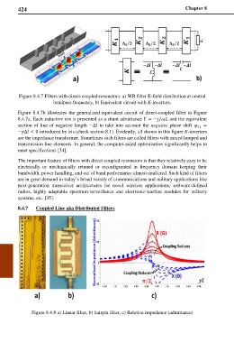
Figure 8.4.7 Filters with direct-coupled-resonators: a) WR filter E-field distribution at central
bandpass ftequency, b) Equivalent circuit with K-inverters.
Figure 8.4.7b illustrates the generalized equivalent circuit of direct-coupled filter in Figure
8.4.7a. Each inductive iris is presented as a shunt admittance = −/ℒ and the equivalent
section of line of negative length −Δ to take into account the negative phase shift 11 =
−Δ < 0 introduced by iris (check section 8.1). Evidently, all shown in this figure K-inverters
are the impedance transformer. Sometimes such filters are called filters with mixed lumped and
transmission line elements. In general, the computer-aided optimization significantly helps to
meet specifications [34].
The important feature of filters with direct-coupled-resonators is that they relatively easy to be
electrically or mechanically retuned or reconfigurated in frequency domain keeping their
bandwidth, power handling, and out of band performance almost unaltered. Such kind of filters
are in great demand in today’s broad varaity of communications and military applications like
next-generation transceiver architectures for novel wireless applications, software-defined
radios, highly adaptable spectrum-surveillance and electronic-warfare modules for military
systems, etc. [35].
8.4.7 Coupled Line aka Distributed Filters
Figure 8.4.8 a) Linear filter, b) hairpin filter, c) Relative impedance (admittance)