
Page 448 - Maxwell House
P. 448
428 Chapter 8
conventional lumped-element filters are very lossy (lower Q), and quarter-wavelength
resonators (higher Q) are too big and unpractical. Pay attention to the cross coupling between
the first and last resonators through the common wall that puts the transmission zeros next to
23
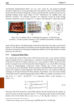
passband realizing steeper slope. Figure 8.4.11b demonstrates the combline filter with
dielectric resonators. The dielectric resonators are commonly excited by probe feeding
structures connected to port1, as Figure 8.4.11c depicts. The idealized E- (black line) and H-
Figure 8.4.11 Combline filters: a) With helical resonators, b) With dielectric
resonators, c) Probe excitation schematic, d) E- and H-field distribution in dielectric
resonator
(solid red line) field as well displacement current (blue dotted line) force lines are pictured in
Figure 8.4.11d. The advantages of such filters are that the high-quality dielectrics like ceramics
provide low dissipation loss and superior temperature stability while the high dielectric constant
guarantees the small size.
8.4.9 Evanescent-Mode Filters
The essential idea of these filters looks a little bit out of the sense: to use sections of hollow
metal waveguide bellow its cutoff frequency as elements of passband filter. We demonstrated
in Sections 6.4 and 6.6 of Chapter 6 that the active energy transfer in WR as well in any other
lossless waveguide turns out to be impossible at these frequencies. As a result, EM wave energy
is stored in nonpropagating (evanescent) modes carrying only reactive energy and
exponentially decaying. Meanwhile, the primary purpose of passband filter is quite the opposite:
to pass active energy at certain frequencies with minimal loss. If so, the evanescent modes are
seemingly not the right nominees for filter enterprise. Nevertheless, let us look more carefully
at their field structure using the dominant TE10-mode in WR as an example. According to (6.23)
and (6.32), = −|| = −�( ) − 1 at frequencies bellow cutoff frequency, i.e.
2
⁄
while < ,
= sin(/) −|| ⎫
0
|| −|| ⎪
= − sin (/) (8.16)
0
0
⎬
/ −||
= cos (/) ⎪
0
0 ⎭
The phase shift of 90 between E- and H-fields indicates that the stored energy and are
°
reactive by nature while the exponential factor −|| characterizes their decay over WR length.
2
⁄
Besides, from (8.16) follows that as soon as > = 2 ⁄ = 2( ) − 1 > 1. It
23 Public Domain Image, source: http://www.jpier.org/PIERL/pierl38/11.13012001.pdf