
Page 447 - Maxwell House
P. 447
MORE COMPLICATED ELEMENTS OF FEED LINES 427
filter may be depicted by way of an array of quarter-wavelength coupled lines, all shorted at
one end and terminated at the other in lumped capacitances as Figure 8.4.9c demonstrates.
Therefore, that is just another variant of coupled filter that has been discussed above. The folded
20
configuration of an 8-stage combline filter is shown in Figure 8.4.9d. Such design allows
implementing quite simple the cross coupling between resonators as the next page Figure
21
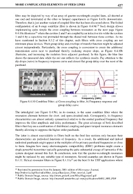
8.4.10a illustrates where the cavities 2 and 5 are coupled by an inductive iris while the cavities
1 and 6 by a capacitive rod protruded through the shared wall between these cavities. As we
have mentioned in Section 8.3.2 of this chapter, such filters with cross coupling are not
minimum phase devices. Their group delay and envelope of transfer function might be adjusted
almost independently. Particularly, the cross coupling is convenient to create the additional
transmission zeros next to passband thereby realizing steeper slope, as Figure 8.4.10b
illustrates, and increasing the isolation from adjacent passband. In this figure, the blue line
shows the measured data while the red one reflects the synthesis results. Pay attention to the
dip drops (zeros) in frequency response curve and almost flat group delay over the most of the
passband.
Figure 8.4.10 Combline Filter: a) Cross-coupling in filter, b) Frequency response and
group delay curve
The interdigital (see Figure 8.4.9b), in its essence, is the same combline filter where the
resonators alternate between the short- and open-circuited ends. Consequently, its frequency
characteristics are almost entirely symmetrical relative to the central passband frequency that
improves the filter amplitude and delay performance. The great advantage of both described
filters that they are a combination of distributed coupling and quasi-lumped resonance elements
thereby allowing to suppress the higher order passbands.
The latter is almost unavoidable in filters built on the feed line sections only because their
characteristics are periodical functions of frequency. As a result, the additional and indeed
undesired passbands might appear at the multiples of the primary passband frequencies or close
to them. Imagine how many electromagnetic compatibility (EMC) problems might create a
single powerful transmitter typically generating the quite substantial energy of harmonics if the
system designer missed this fact. In conclusion, note that the quarter-wavelength resonators
might be replaced by any suitable type of resonators. Several examples are shown in Figure
8.4.11. Helical resonator filters in Figure 8.4.11a are the best fit for UHF applications where
22
20 Reprinted by permission from the January, 2001 edition of Microwave Journal,
http://traktoria.org/files/radio/filter_design/Bandpass_Filter_tutorial_2.pdf
21 Public Domain Image, source: http://www.gwtsoft.com/Misc/Hagensen3.pdf
22 Public Domain Image, source: http://maxwell.uwaterloo.ca/~myu/publications/04EU_HEL.PDF