Page 454 - Maxwell House
P. 454

434                                                                Chapter 8


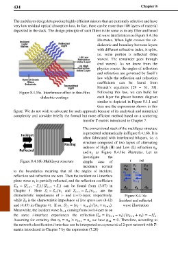
        The multilayer design lets produce highly efficient mirrors that are extremely selective and have
        very low residual optical absorption loss. In fact, there can be more than 100 layers of material
        deposited in the stack. The design principle of such filters is the same as in any filter and based
                                                    on wave interferences as Figure 8.4.16a
                                                    illustrates. When light crosses the air-
                                                    dielectric and boundary between layers
                                                    with different refractive index, it splits,
                                                    i.e. some portion is reflected (blue
                                                    waves). The remainder goes through
                                                    (red waves). As  we know  from the
                                                    physics course, the angles of reflection
                                                    and refraction are governed by Snell’s
                                                    law while the reflection and refraction
                                                    coefficients  can  be found  from
                                                    Fresnel’s equations [29  –  31, 33].
           Figure 8.4.16a  Interference effect in thin-film   Following this  law,  we can  build for
                      dielectric coatings           each layer the phasor bounce diagram
                                                    similar to depicted in Figure 8.1.1 and
                                                    then use the expressions shown in this
        figure. We do not wish to advocate for such approach because of its analytical and numerical
        complexity and consider briefly the formal but more efficient method based on a scattering
                                             transfer T-matrix introduced in Chapter 7.
                                             The conventional stack of the multilayer structure
                                             is presented schematically in Figure 8.4.16b. It is
            Incident
                                             often fabricated with interleaved bilayers, i.e. a
                                   Passing   structure composed of two layers of alternating
           Reflected                         indexes of High (H) and Low (L) refraction 
                                                                                   
                                             and    as Figure 8.4.16c illustrates.  Let us
                                                 
                                             investigate  the
            Figure 8.4.16b Multilayer structure   simple  case  of
                                             incidence normal
        to the boundaries  meaning that  all  the  angles  of  incident,
        reflection and refraction are zero. Then the incident on i-interface
        plane wave   is partially reflected, and the reflection coefficient
                   
         
                       ⁄
         11  = ( +1  −  ) ( +1  +  )  can  be  found  from  (3.87)  in
                                
                     
        Chapter 3. Here   =  /   and   +1  =  / +1   are the
                                               0
                              0
                          
                                 
        characteristic impedances of  i-  and (i+1)-layer, respectively,   Figure 8.4.16c
        while   is the characteristic impedance of free space (see (4.42)   Incident and reflected
              0
                                    
                                                 ⁄
        and (4.43) in Chapter 4).  If so,   11  = ( −  +1 ) ( +  +1 ).   wave illustration
                                          
                                                    
        Meanwhile, the incident wave  +1  coming from (i+1)-layer to on
                                                                                  
                                                     
                                                                  ⁄
        the same  i-interface experiences  the reflection  22  = ( +1  −  ) ( +1 +  ) = − .
                                                                                  11
                                                                 
                                                                           
        Assuming for certainty that  =  >  +1  =   we have  11  = 0. Therefore, according to


        the network classification i-interface can be interpreted as asymmetrical 2-port network with T-
        matrix introduced in Chapter 7 by the expression (7.20)
   449   450   451   452   453   454   455   456   457   458   459