
Page 456 - Maxwell House
P. 456
436 Chapter 8
Even in the case when the thin-film technology allows handling wider spectrum of optically
transparent dielectric materials than listed in Table 8.4, we cannot expect that the required
material exists or its development is too expensive. The way around is to replace each single
layer of nonexistent index “… with an equivalent set of three layers of available indices and
appropriate thicknesses” [33]. This greater freedom creates opportunities to develop more
advanced but naturally more
expensive filters. Nevertheless,
the key filter design principle is
not changed: the stack of
alternating films laying on top
of each other initiates the
multiple reflected and refracted
waves. If so, adjusting the layer
number, their refractive index
and thicknesses we may achieve
the required passband
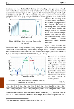
Figure 8.4.16d Multilayer band-pass filter transfer transparency and/or stopband
characteristic reflectivity.
Figure 8.4.17 illustrates the
characteristic of the exemplary mirror passing through the light of wavelengths around 1490
31
nm and 1550 nm while reflecting almost entirely the light around 1310 nm . The refractive
index of each layer is listed in Table 8.5. It was assumed that all light signals come from the air
( = 1) and complete their way inside the fiber ( 14 = 1.4475).
1
Most aspects of dichroic
mirrors and other optical
filters are far beyond the
scope of this course, and
we hope that the excellent
book [33] published on-
line could help the reader to
grasp on the subject. Also,
this book offers extensive
references of 1858 titles in
all areas related to
electrodynamics.
Figure 8.4.17 Transparent and reflective characteristic of
synthesized dichroic mirror Table 8.5
Note in conclusion that the transfer scattering matrix defined by (8.18) and (8.19) keeps its
structure with some adjustments and mean for the oblique incidence and lossy materials [33].
31 This optical filter was synthesized using the Matlab code from [33]