Page 85 - Hot Runner & Control Systems 2020
P. 85

Straight-Shot Hot Sprue Bushings                                        83


                                            E-Series Straight-Shot            ™


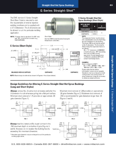
            The DME standard E-Series Straight-                                     E-Series Straight-Shot Hot
            Shot (Short Style) is  intended to suit                                 Sprue Bushings (Short Style)
            the requirements of smaller injection
            molding machines and is supplied with                                     WITH 240 VOLT   R     A
                                                                                        HEATER
            a /8" A dimension. The A dimension can                                                      DIMENSION
             7
            be altered to suit the particular molding                                 ITEM NUMBER   1
            application.                                                               SSBT4407E2    ⁄2     7 ⁄8
                                                                                       SSBT0407E2  NONE
            NOTE:  5° heater lead is standard. For 90° lead,   Short Style              NOTE:
                 add “90” to end of item number (e.g.,   See the DME Control Systems Catalog for   The expansion factor must be taken
                 SSBT4407E290).                 temperature controllers.                into consideration prior to machining
                                                                                        for and installation of the bushing.
                                                                                        This factor (BE) must then be added
            E-Series (Short Style)                    3.22                              to the A dimension. The formula for
                                                                                        determining this expansion factor is
                                         7                   +.000                      as follows:
                                      A =  8           1.995 DIA. –.005  .19
            .25 LAND                                                                     BE = “A” dimension x 0.00000633
                                   .015 RELIEF                                           x nozzle set point - 68ºF (assuming
                                                                                         the mold is at 68ºF during
                                                                                         operation). If mold temperature
            .06 DIA.                  .06                                                is different, substitute 68ºF with
                                 1.000   DIA.           .25 DIA.                         actual mold temperature.
                                   DIA.                                 R
                                                                                        EXAMPLE:
                                                                                        Given a setpoint of 500°F:
                                        .25                                              BE = 1.375 × .0000063 × (500 – 68) =
                                                                                         .004 thus 1.375 + .004 = 1.379.
                                             .44                      .340              Please note that the above
                                                                                        information is given as an example.
             ENLARGED VIEW AS SUPPLIED          SSBT4407E2                  SSBT0407E2  Variations may occur based on mold
                                                                                        configuration and  cooling factor. In
            NOTE: Must always be altered as shown in Figures 1 thru 6 (see below).      some instances, it may be necessary
                                                                                        to obtain an empirical factor.

            Design Guidelines for Altering E-Series Straight-Shot Hot Sprue Bushings                                  Hot Runner Systems   |    4-Zone and 8-Zone Timer-Based Sequencers
            (Long and Short Styles)

            Always remove the .25 extra stock allowance and alter the   Maximum stock removal of .268 provides an approximate
            A dimension to suit whenever gating into a flat part  surface.   .08 gate diameter (Figure 2). Maximum stock removal of
            Minimum stock removal of .25 provides an approximate .06   .268 is recommended for gate diameters larger than .08
            gate diameter (Figure 1).                           (Figures 3 and 4).
                  .25                     .268                    .268                    .268
                  MIN.                    MAX.                    MAX.                    MAX.
                  DEPTH                   DEPTH                   DEPTH                   DEPTH
             .06 DIA.                .08 DIA.                .09 DIA.                .12 DIA.

                                                                                                                       Straight-Shot Hot Sprue Bushings   |    E-Series Straight-Shot ™


                           FIG. 1                   FIG. 2                   FIG. 3                 FIG. 4
            Always machine runner profile or part contour to the   .268                   .268
                                                                                          MAX.
                                                                MAX.
            .268 maximum depth at centerline of gate (Figures 5   DEPTH                   DEPTH
            and 6). However, do not weaken the bushing face by   *GATE DIA.        *GATE DIA.
            exceeding this maximum dimension.

            * Resultant gate diameter may be enlarged to suit the particular
             molding application.
                                                                      FIG. 5                       FIG. 6

             U.S. 800-626-6653  n Canada 800-387-6600  n dme@milacron.com  n www.milacron.com
   80   81   82   83   84   85   86   87   88   89   90