
Page 449 - StudyBook.pdf
P. 449
Topologies and IDS • Chapter 7 433
■ Layered DMZ implementation
■ Multiple interface firewall implementation
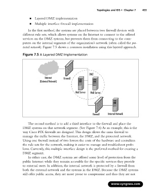
In the first method, the systems are placed between two firewall devices with
different rule sets, which allows systems on the Internet to connect to the offered
services on the DMZ systems, but prevents them from connecting to the com-
puters on the internal segments of the organization’s network (often called the pro-
tected network). Figure 7.5 shows a common installation using this layered approach.
Figure 7.5 A Layered DMZ Implementation
DMZ
Internet Firewall
(External Network)
Mail Server Web Server
Firewall Internal Network
The second method is to add a third interface to the firewall and place the
DMZ systems on that network segment. (See Figure 7.6) As an example, this is the
way Cisco PIX firewalls are designed.This design allows the same firewall to
manage the traffic between the Internet, the DMZ, and the protected network.
Using one firewall instead of two lowers the costs of the hardware and centralizes
the rule sets for the network, making it easier to manage and troubleshoot prob-
lems. Currently, this multiple interface design is the preferred method for creating a
DMZ segment.
In either case, the DMZ systems are offered some level of protection from the
public Internet while they remain accessible for the specific services they provide
to external users. In addition, the internal network is protected by a firewall from
both the external network and the systems in the DMZ. Because the DMZ systems
still offer public access, they are more prone to compromise and thus they are not
www.syngress.com