
Page 231 - Wago_AutomationTechnology_Volume3_2015_US.pdf
P. 231
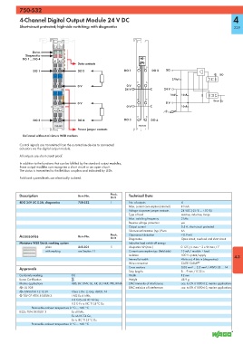
750-532

           4-Channel Digital Output Module 24 V DC                                                                 4

           Short-circuit protected; high-side switching; with diagnostics                                           229


                            13  14
                 Status    A   E
                            B  F
             Diagnostics   C   G
            DO 1 ... DO 4  D   H
                            A1 A2
                                       Data contacts
                                                                    1    5
                 DO 1                  DO 2                   DO 1         DO 2   DO
                                                                                                             DO
                            -  -
                                                                                     270pF
                                                                    2    6
                                       0 V                     0 V
                                                              24 V               24 V
                            -  -
                                                                                    10nF  10nF
                                                                    3    7                                Error
                                       0 V                                        0 V
                                                               0 V                        10nF
                            A3 A4
                                                                    4    8
                 DO 3                  DO 4                   DO   3        DO 4
                            750-532                                  750-532
                                       Power jumper contacts
            Delivered without miniature WSB markers

           Control signals are transmitted from the automation device to connected
           actuators via the digital output module.
           All outputs are short-circuit proof.

           In addition to the functions that can be fulfilled by the standard output modules,
           these output modules can recognize a short circuit or an open circuit.
           The status is transmitted to the fieldbus couplers and indicated by LEDs.
           Field and system levels are electrically isolated.


           Description                 Item No.        Pack.    Technical Data
                                                       Unit
           4DO 24V DC 0.5A, diagnostics  750-532       1        No. of outputs            4
                                                                Max. current consumption (internal)  10 mA
                                                                Voltage via power jumper contacts  24 VDC (-25 % ... +30 %)
                                                                Type of load              resistive, inductive, lamps
                                                                Max. switching frequency  2 kHz
                                                                Reverse voltage protection  yes
                                                                Output current            0.5 A, short-circuit protected
                                                                Short-circuit limitation (typ.) Pwm  6A
           Accessories                 Item No.        Pack.    Open-circuit detection    < 0.9 mA
                                                       Unit     Diagnostics               Open-circuit, overload and short-circuit
           Miniature WSB Quick marking system                   Inductive load switch off energy
                       plain           248-501         5        dissipation W (max.)      0.125 J; L max = 2 x W max / I 2
                       with marking    see Section 11           Current consumption typ. (field side)  13 mA / module + load
                                                                Isolation                 500 V system/supply       4.3
                                                                Internal bit width        4 bits out, 4 bits in (diagnostics)
                                                                Wire connection           CAGE CLAMP ®
           Approvals                                            Cross sections            0.08 mm² ... 2.5 mm² / AWG 28 ... 14
                                                                Strip lengths             8 ... 9 mm / 0.33 in
           Conformity marking       1                           Width                     12 mm
           Korea Certification                                  Weight                    48.9 g
           Marine applications      ABS, BV, DNV, GL, KR, LR, NKK, PRS, RINA  EMC immunity of interference  acc. to EN 61000-6-2, marine applications
           r UL 508                                             EMC emission of interference  acc. to EN 61000-6-3, marine applications
           r ANSI/ISA 12.12.01      Class I, Div. 2, Grp. ABCD, T4
           4 TÜV 07 ATEX 554086 X   I M2 Ex d I Mb,
                                    II 3 G Ex nA IIC T4 Gc,
                                    II 3 D Ex tc IIIC T135°C Dc
                 Permissible ambient temperature 0 °C ... +60 °C
           IECEx TUN 09.0001 X      Ex d I Mb,
                                    Ex nA IIC T4 Gc,
                                    Ex tc IIIC T135°C Dc
                 Permissible ambient temperature 0 °C ... +60 °C