
Page 234 - Wago_AutomationTechnology_Volume3_2015_US.pdf
P. 234
750-537 / 753-537
4 8-Channel Digital Output Module 24 V DC
232 Short-circuit protected; high-side switching; with diagnostics
Status 13 14
Diagnostics
DO 1 ... DO 8 A B E F
C G
D H
A1 A2
Data contacts
1 5
DO 1 DO 2 DO 1 DO 2 DO
Status
A3 A4
270pF µC
2 6 Status
DO 3 DO 4 DO 3 DO 4 Diag.
24 V 24 V
Diagnostics
A5 A6 10nF 10nF
3 7
DO 5 DO 6 DO 5 DO 6
0 V 0 V
10nF
A7 A8
4 8
DO 7 DO 8 DO 7 DO 8
750-537 750-537
Power jumper contacts
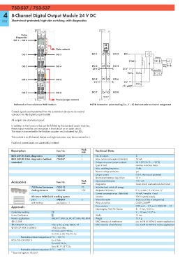
Delivered without miniature WSB markers NOTE: Connection point marking (i.e., 1 ... 8) does not refer to channel assignment
Control signals are transmitted from the automation device to connected
actuators via the digital output module.
All outputs are short-circuit proof.
In addition to the functions that can be fulfilled by the standard output modules,
these output modules can recognize a short circuit or an open circuit.
The status is transmitted to the fieldbus couplers and indicated by LEDs.
The module is an 8-channel device and eight actuators may be connected to it.
Field and system levels are electrically isolated.
Description Item No. Pack. Technical Data
Unit
8DO 24V DC 0.5A, diagnostics 750-537 1 No. of outputs 8
8DO 24V DC 0.5A, diagnostics (without 753-537 1 Max. current consumption (internal) 50 mA
connector) Voltage via power jumper contacts 24 V DC (-25 % ... +30 %)
Type of load resistive, inductive, lamps
Max. switching frequency 1 kHz
Reverse voltage protection yes
Output current 0.5 A, short-circuit protected
Short-circuit limitation (typ.) Pwm 12 A
Accessories Item No. Pack. Open-circuit detection < 0.1 mA
Unit Diagnostics Open-circuit, overload and short-circuit
753 Series Connectors 753-110 25 Inductive load switch off energy
Coding elements 753-150 100 dissipation W (max.) 0.1 J; L max = 2 x W max / I 2
Current consumption typ. (field side) 16 mA / module + load
Miniature WSB Quick marking system Isolation 500 V system/supply
plain 248-501 5 Internal bit width 8 bits out, 8 bits in (diagnostics)
with marking see Section 11 Wire connection CAGE CLAMP ®
Approvals Cross sections 0.08 mm² ... 2.5 mm² / AWG 28 ... 14
Strip lengths, 750/753 Series 8 ... 9 mm / 0.33 in
Conformity marking 1 9 ... 10 mm / 0.37 in
Korea Certification Width 12 mm
1)
1)
Marine applications ABS, BV , DNV, GL, KR, LR , NKK, PRS, RINA Weight 51.9 g
r UL 508 EMC immunity of interference acc. to EN 61000-6-2, marine applications
r ANSI/ISA 12.12.01 Class I, Div. 2, Grp. ABCD, T4 EMC emission of interference acc. to EN 61000-6-3, marine applications
4 TÜV 07 ATEX 554086 X I M2 Ex d I Mb,
II 3 G Ex nA IIC T4 Gc,
II 3 D Ex tc IIIC T135°C Dc
Permissible ambient temperature 0 °C ... +60 °C
IECEx TUN 09.0001 X Ex d I Mb,
Ex nA IIC T4 Gc,
Ex tc IIIC T135°C Dc
Permissible ambient temperature 0 °C ... +60 °C
1)
Does not apply to 753-537