
Page 236 - Wago_AutomationTechnology_Volume3_2015_US.pdf
P. 236
750-1506
750-1506
4 8-Channel Digital Input/Output Module 24 V DC
234 High-side switching
750-1506
750-1506
13 14
1 2
3 4
5 6
Status 7 8
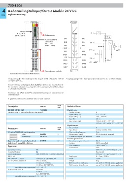
9 10 DI
DI 1 ... DI 8 11 12
DO 1 ... DO 8 13 14 Data contacts
15 16
1 2
DI 1 DI 2
®
CAGE CLAMP S DI
3 4
connection DI 3 DI 4
DI 1 ... DI 8 DO
5 6
DO 1 ... DO 8 DI 5 DI 6
270 pF
+ 24 V
7 8 24 V DO
DI 7 DI 8
9 10 10 nF
DO 1 DO 2
0 V
0 V
11 12
DO 3 DO 4 10 nF
13 14
DO 5 DO 6
15 16
DO 7 DO 8
Power jumper contacts
Delivered without miniature WSB markers
The digital input/output module provides 8 inputs and 8 outputs at a width of An optocoupler provides electrical isolation between the bus and the field side.
just 12mm (0.47in.).
It receives binary control signals from digital field devices and transmits them to
the connected actuators (e.g., magnetic valves, contactors, transmitters, relays
or other electrical loads).
®
The module has CAGE CLAMP S connections enabling solid conductors to be
inserted directly.
A green LED indicates the switched status of each channel.
Description Item No. Pack. Technical Data
Unit
8DI 8DO 24V DC 0.5A 750-1506 1 Digital inputs:
Interference-free for use in safety functions (see manual) Number of inputs 8
Signal voltage (0) -3 V ... +5 V DC
Signal voltage (1) 15 V ... 30 V DC
Input filter 3.0 ms
Input current (typ.) +0.6 mA (at -3 V ... +5 V DC)
+2.2 mA ... +2.5 mA (at 15 V ... +32 V DC)
Digital outputs:
Accessories Item No. Pack. No. of outputs 8
Unit Type of load resistive, inductive, lamps
Miniature WSB Quick marking system Max. switching frequency 1kHz
plain 248-501 5 Output current (max.) 0.5 A, short-circuit protected
with marking see Section 11 Current consumption typ. (field side) 16mA
General Specifications
Operating tool, with partially insulated 210-719 50 Current consumption (internal) 30 mA
shaft, type 1, blade (2.5 x 0.4) mm Isolation 500 V system/field
®
Approvals Wire connection CAGE CLAMP S
Cross sections solid:
Conformity marking 1 0.08 mm² ... 1.5 mm² / AWG 28 ... 16
Korea Certification fine-stranded:
Marine applications ABS, BV, DNV, GL, KR, LR, NKK, PRS, RINA 0.25 mm² ... 1.5 mm² / AWG 22 ... 16
r UL 508 Strip lengths 8 ... 9 mm / 0.33 in
r ANSI/ISA 12.12.01 Class I, Div. 2, Grp. ABCD, T4 Width 12 mm
4 TÜV 07 ATEX 554086 X I M2 Ex d I Mb, Weight 60 g
II 3 G Ex nA IIC T4 Gc, EMC immunity of interference acc. to EN 61000-6-2, marine applications
II 3 D Ex tc IIIC T135°C Dc EMC emission of interference acc. to EN 61000-6-3, marine applications
Permissible ambient temperature 0 °C ... +60 °C
IECEx TUN 09.0001 X Ex d I Mb,
Ex nA IIC T4 Gc,
Ex tc IIIC T135°C Dc
Permissible ambient temperature 0 °C ... +60 °C