Page 278 - Wago_AutomationTechnology_Volume3_2015_US.pdf
P. 278

750-491

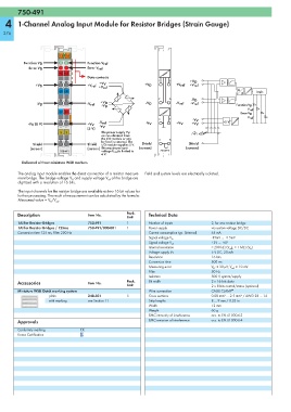
   4    1-Channel Analog Input Module for Resistor Bridges (Strain Gauge)

  276


                          13  14
                         A
           Function V D      C       Function V ref
                         B
             Error V D       D       Error V ref
                         +UD +UR
                                     Data contacts
                                                                  1   5        +V D
                                          +V V
                +V D                 +V ref                 +V D         +V ref  +V ref
                                         +V ref
                                                                                                  A
                         -UD  -UR                                                                         Logic
                                                                                                    D
                                                                  2   6        -V D
                                          +V D               -V D        -V ref
                -V D                 -V ref                                    -V ref
                                           -V D                                                   Function V D
                                                                                                      V ref
                         0V  5V
                                                                                                   Error V D
                                                                                                      V ref
                                                                  3   7         -V V
                                          -V ref                                            +5 V
             -V V  (0 V)             +V V                    -V V        +V V  +V V
                                     (5 V)  -V V
                          S   S            The power supply V V
                                           can be obtained from
                                           the I/O module or can   4   8
                                           be feed in external. The
              Shield                 Shield  I/O module supplies 5 V.  Shield   Shield
             (screen)                (screen) The maximum input   (screen)   (screen)
                          750-491          voltage U ref  is limited to   750-491
                                           6 V.
          Delivered without miniature WSB markers
        The analog input module enables the direct connection of a resistor measure-  Field and system levels are electrically isolated.
        ment bridge. The bridge voltage V  and supply voltage V  of the bridge are
                              D              ref
        digitized with a resolution of 16 bits.
        The input channels for the resistor bridge are available as two 16 bit values for
        further processing. The result of measurement can be calculated by the formula:
        Measured value = V /V .
                      D  ref
        Description                  Item No.        Pack.    Technical Data
                                                     Unit
        1AI for Resistor Bridges     750-491         1        Number of inputs         2, for one resistor bridge
        1AI for Resistor Bridges / 125ms  750-491/000-001  1  Power supply             via system voltage DC/DC
        Conversion time 125 ms, Filter 200 Hz                 Current consumption typ. (internal)  65 mA
                                                                                       -15mV ... +15mV
                                                              Signal voltage V D
                                                                                       +2V ... +6V
                                                              Signal voltage V ref
                                                              Internal resistance      > 200 kΩ (V ref ), > 1 MΩ (V D )
                                                              Voltage supply Vv        5 V DC, 20 mA
                                                              Resolution               16 bits
                                                              Conversion time          500 ms
                                                              Measuring error          V D : ± 30 μV; V ref : ± 10 mV
                                                              Filter                   50 Hz
                                                              Isolation                500 V system/supply
        Accessories                  Item No.        Pack.    Bit width                2 x 16 bits data
                                                     Unit                              2 x 8 bits control/status (optional)
        Miniature WSB Quick marking system                    Wire connection          CAGE CLAMP ®
                     plain           248-501         5        Cross sections           0.08 mm² ... 2.5 mm² / AWG 28 ... 14
                     with marking    see Section 11           Strip lengths            8 ... 9 mm / 0.33 in
                                                              Width                    12 mm
                                                              Weight                   60 g
                                                              EMC immunity of interference  acc. to EN 61000-6-2
        Approvals                                             EMC emission of interference  acc. to EN 61000-6-4
        Conformity marking        1
        Korea Certification
   273   274   275   276   277   278   279   280   281   282   283