
Page 280 - Wago_AutomationTechnology_Volume3_2015_US.pdf
P. 280
750-494
4 3-Phase Power Measurement Module
278
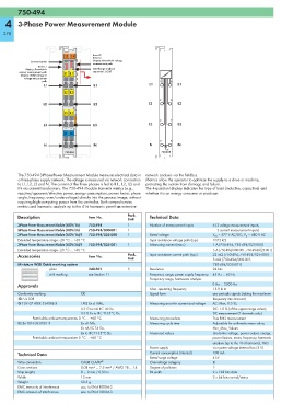
13 14 Error L2
Error L3
Communication A E Display: Override in voltage
B F measurement path
Error L1 C G
Display: Override in D H Interchange in phase
current measurement path L1 IL1 sequence L1-L2-L3
Display: Undervoltage in
voltage measurement
path
L1 IL1 L1 IL1
L2 IL2
L2 IL2 L2 IL2
L3 IL3
L3 IL3 L3 IL3
N IN
N IN N IN
750-494 750-494
The 750-494 3-Phase Power Measurement Module measures electrical data in network analysis via the fieldbus.
a three-phase supply network. The voltage is measured via network connection Metrics allow the operator to optimize the supply to a drive or machine,
to L1, L2, L3 and N. The current of the three phases is fed to IL1, IL2, IL3 and protecting the system from damage and failure.
IN via current transformers. The 750-494 Module transmits metrics (e.g., The 4-quadrant display indicates the type of load (inductive, capacitive) and
reactive/apparent/effective power, energy consumption, power factor, phase whether it is an energy consumer or producer.
angle, frequency, over-/undervoltage) directly into the process image, without
requiring high computing power from the controller. Both comprehensive
metrics and harmonic analysis up to the 41st harmonic permit an extensive
Description Item No. Pack. Technical Data
Unit
3-Phase Power Measurement Module (480V/1A) 750-494 1 Number of measurement inputs 6 (3 voltage measurement inputs,
3-Phase Power Measurement Module (480V/5A) 750-494/000-001 1 3 current measurement inputs)
3-Phase Power Measurement Module (480V/1A)/T 750-494/025-000 1 Rated voltage V LN = 277 V AC/DC; V LL = 480 V AC
Extended temperature range: -20 °C ... +60 °C Input resistance voltage path (typ.) 1072 kΩ
3-Phase Power Measurement Module (480V/5A)/T 750-494/025-001 1 Measuring current (max.) 1 A (750-494, 750-494/025-000)
Extended temperature range: -20 °C ... +60 °C 5 A (750-494/000-001, 750-494/025-001)
Accessories Item No. Pack. Input resistance current path (typ.) 22 mΩ (750-494, 750-494/025-000)
Unit 5 mΩ (750-494/000-001,
Miniature WSB Quick marking system 750-494/025-001)
plain 248-501 5 Resolution 24 bits
with marking see Section 11 Frequency range, power supply frequency 45 Hz ... 65 Hz
Frequency range, harmonics analysis
Approvals 0 Hz ... 3300 Hz
Max. operating frequency 15.9 kHz
Conformity marking 1 Signal form any periodic signals (taking the maximum
r UL 508 frequency into account)
4 TÜV 07 ATEX 554086 X I M2 Ex d I Mb, Measuring error for current and voltage AC: Max. 0.5 %;
II 3 G Ex nA IIC T4 Gc, DC: 1.0 % (of the upper range value);
II 3 D Ex tc IIIC T135°C Dc DC measurement (2 channels only)
Permissible ambient temperature 0 °C ... +60 °C Measuring procedure True RMS measurement
IECEx TUN 09.0001 X Ex d I Mb, Measuring cycle time Adjustable for arithmetic mean value,
Ex nA IIC T4 Gc, Min_Max_Values
Ex tc IIIC T135°C Dc Measured values Line-to-line voltage, power output, energy,
Permissible ambient temperature 0 °C ... +60 °C power factors, mains frequency, harmonic
analysis (up to the 41st harmonic), THD
Power supply via system voltage internal bus (5 V)
Technical Data Current consumption (internal) 100 mA
Rated surge voltage 4 kV
Wire connection CAGE CLAMP ® Overvoltage category III
Cross sections 0.08 mm² ... 2.5 mm² / AWG 28 ... 14 Degree of pollution 2
Strip lengths 8 ... 9 mm / 0.33 in Bit width 2 x 128 bits data
Width 12 mm 2 x 64 bits control/status
Weight 50.5 g
EMC immunity of interference acc. to EN 61000-6-2
EMC emission of interference acc. to EN 61000-6-3