Page 279 - Wago_AutomationTechnology_Volume3_2015_US.pdf
P. 279

750-493

           3-Phase Power Measurement Module                                                                        4

                                                                                                                    277


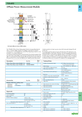
                              13 14      Low voltage L2
                                         Low voltage L3
                Communication  A  E      Display: Override in voltage
                              B  F       measurement path
                Low voltage L1  C  G
              Display: Override in   D  H  Interchange in phase
           current measurement path  L1 IL1  sequence L1-L2-L3
            Display: Undervoltage in     Data contacts
             voltage measurement
                    path                                            1    5
                     L1                  IL1                    L1         IL1
                                                   L1
                              L2 IL2
                                                                    2    6
                     L2                  IL2                    L2         IL2
                                                      L2
                              L3 IL3
                                                                    3    7
                     L3                  IL3                    L3         IL3
                                                         L3
                              N IN
                                                                    4    8
                     N                   IN                     N          IN
                              750-493                                750-493

            Delivered without miniature WSB markers

           The 750-493 3-Phase Power Measurement Module measures the electrical   module using the root mean square values of all measured voltages (V) and
           data in a 3-phase supply network. The voltage is measured via network   currents (I).
           connection to L1, L2, L3 and N. The current of the three phases is fed to IL1, IL2,  For example, both the apparent power (S) and phase shift angle (ϕ) can be
           IL3 and IN via current transformers.                easily derived from these values. Therefore, the 3-phase power measurement
           The 3-phase power measurement module transmits the root mean square values  module provides a comprehensive network analysis via the fieldbus. By means
           into the process image without requiring high computing power from the cont-  of values such as voltage, current, effective and apparent power consumption
           roller. For each phase, the effective power (P), the energy consumption (W) and  or load condition, the operator can regulate the supply to a drive or machine
           the power factor (cos ϕ) are calculated by the 3-phase power measurement   in the best possible way and protect the installation from damage/failure.
           Description                 Item No.        Pack.    Technical Data
                                                       Unit
           3-Phase Power Measurement Module (1 A)  750-493  1   Number of measurement inputs  6 (3 voltage measurement inputs,
           3-Phase Power Measurement Module (5 A)  750-493/000-001  1                      3 current measurement inputs)
                                                                Rated voltage             V LN  = 277 V AC/DC; V LL  = 480 V AC
                                                                Input resistance voltage path (typ.)  1071 kΩ
                                                                Measuring current (max.)  1 A (750-493)
                                                                                          5 A (750-493/000-001)
                                                                Input resistance current path (typ.)  22 mΩ (750-493)
                                                                                          5 mΩ (750-493/000-001)
                                                                Resolution                16 bits
                                                                Frequency range with activated DC filter  10 Hz … 2000 Hz
                                                                Frequency range with deactivated DC
                                                                filter                    0 Hz … 2000 Hz
           Accessories                 Item No.        Pack.    Max. operating frequency  7.2 kHz
                                                       Unit     Signal form               any (in consideration of the maximum
           Miniature WSB Quick marking system                                             operating frequency)
                       plain           248-501         5        Measuring error for current and voltage  AC: Max 0.5 %; DC: 1.0 % (of the upper range value)
                       with marking    see Section 11           Measuring procedure       True RMS measurement
                                                                Measuring cycle time      Adjustable for measured value,
                                                                                          Min_Max_Values
                                                                Measured values           Effective power, energy,
           Approvals                                                                      power factor (cos ϕ)
                                                                Power supply              via system voltage internal bus (5 V)
           Conformity marking       1                           Current consumption (internal)  100 mA
           Korea Certification                                  Rated surge voltage       4 kV                      4.4
           r UL 508                                             Overvoltage category      III
           4 TÜV 07 ATEX 554086 X   I M2 Ex d I Mb,             Degree of pollution       2
                                    II 3 G Ex nA IIC T4 Gc,     Bit width                 2 x 48-bit data,
                                    II 3 D Ex tc IIIC T135°C Dc                           2 x 24-bit control/status (option)
                 Permissible ambient temperature 0 °C ... +60 °C  Wire connection         CAGE CLAMP ®
           IECEx TUN 09.0001 X      Ex d I Mb,                  Cross sections            0.08 mm² ... 2.5 mm² / AWG 28 ... 14
                                    Ex nA IIC T4 Gc,            Strip lengths             8 ... 9 mm / 0.33 in
                                    Ex tc IIIC T135°C Dc        Width                     12 mm
                 Permissible ambient temperature 0 °C ... +60 °C  Weight                  48.5 g
                                                                EMC immunity of interference  acc. to EN 61000-6-2
                                                                EMC emission of interference  acc. to EN 61000-6-3
   274   275   276   277   278   279   280   281   282   283   284