
Page 281 - Wago_AutomationTechnology_Volume3_2015_US.pdf
P. 281
750-495
3-Phase Power Measurement Module 4
279
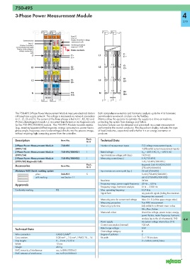
13 14 15 16 Error L2
Error L3
Communication A E A E Display: Override in voltage
B F B F measurement path
Error L1 C G C G
Display: Override in D H D H Interchange in phase
current measurement path L1 I1+ I1- sequence L1-L2-L3
Display: Undervoltage in Data contacts
voltage measurement
path I1-
L1 I1- L1 I1+
I1+
L2 I2+ I2-
I2-
L2 I2- L2 I2+
I2+
L3 I3+ I3-
I3-
L3 I3- L3 I3+
I3+
N IN+ IN-
N IN- N IN-
IN+
IN+
750-495 750-495
The 750-495 3-Phase Power Measurement Module measures electrical data in Both comprehensive metrics and harmonic analysis up to the 41st harmonic
a three-phase supply network. The voltage is measured via network connection permit extensive network analysis via the fieldbus.
to L1, L2, L3 and N. The current of the three phases is fed to IL1, IL2, IL3 and Metrics allow the operator to optimize the supply to a drive or machine,
IN (two clamping points each +,-) via current transformers or via Rogowski coils protecting the system from damage and failure.
for the 750-495/000-002 module. The 750-495 Module transmits metrics Insulation failures can be detected and prevented via current measurement
(e.g., reactive/apparent/effective power, energy consumption, power factor, performed in the neutral conductor. The 4-quadrant display indicates the type
phase angle, frequency, over-/undervoltage) directly into the process image, of load (inductive, capacitive) and whether it is an energy consumer or
without requiring high computing power from the controller. producer.
Description Item No. Pack. Technical Data
Unit
3-Phase Power Measurement Module 750-495 1 Number of measurement inputs 7 (3 voltage measurement inputs,
(690V/1A) 4 differential current measurement inputs)
3-Phase Power Measurement Module 750-495/000-001 1 Rated voltage V LN = 400 V AC; V LL = 690 V AC
(690V/5A) Input resistance voltage path (typ.) 1429 kΩ
3-Phase Power Measurement Module 750-495/000-002 1 Measuring current (max.) 1 A (750-495)
(690V/RC) Rogowski Coils 5 A (750-495/000-001)
Accessories Item No. Pack. Rogowski Coils RT500/RT2000
Unit (750-495/000-002)
Miniature WSB Quick marking system Input resistance current path (typ.) 22 mΩ (750-495)
plain 248-501 5 5 mΩ (750-495/000-001)
with marking see Section 11 44 kΩ (750-495/000-002)
Resolution 24 bits
Approvals Frequency range, power supply frequency 45 Hz ... 65 Hz
Frequency range, harmonics analysis 0 Hz … 3300 Hz
Conformity marking 1 Max. operating frequency 15,9 kHz
Signal form any periodic signals (taking the maximum
frequency into account)
Measuring error for current and voltage Max. 0.5 % (of the upper range value)
Measuring procedure True RMS measurement
Measuring cycle time Adjustable for arithmetic mean value,
Min_Max_Values
Measured values Line-to-line voltage, power output, energy,
power factors, mains frequency, harmonic
analysis (up to the 41st harmonic), THD 4.4
Power supply via system voltage internal bus (5 V)
Current consumption (internal) 100 mA
Technical Data Rated surge voltage 6 kV
Overvoltage category III
Wire connection CAGE CLAMP ® Degree of pollution 2
Cross sections 0.08 mm² ... 2.5 mm² / AWG 28 ... 14 Bit width 2 x 128 bits data
Strip lengths 8 ... 9 mm / 0.33 in 2 x 64 bits control/status
Width 12 mm
Weight 48.5 g
EMC immunity of interference acc. to EN 61000-6-2
EMC emission of interference acc. to EN 61000-6-3