
Page 354 - Wago_AutomationTechnology_Volume3_2015_US.pdf
P. 354
750-535
750-535
4 2-Channel Digital Output Module 24 V DC, Ex i
352 Short-circuit protected; PNP-positive switching
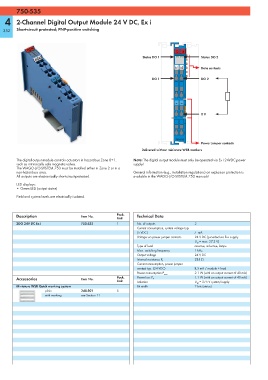
13 14
Status DO 1 Status DO 2
A1 A2 Data contacts
DO 1 DO 2
— —
0 V
750-535
Power jumper contacts
Delivered without miniature WSB markers
The digital output module controls actuators in hazardous Zone 0+1. Note: The digital output module must only be operated via Ex i 24VDC power
such as intrinsically safe magnetic valves. supply!
The WAGO-I/O-SYSTEM 750 must be installed either in Zone 2 or in a
non-hazardous area. General information (e.g., installation regulations) on explosion protection is
All outputs are electronically short-circuit-protected. available in the WAGO-I/O-SYSTEM 750 manuals!
LED displays:
• Green LED (output status)
Field and system levels are electrically isolated.
Description Item No. Pack. Technical Data
Unit
2DO 24V DC Ex i 750-535 1 No. of outputs 2
Current consumption, system voltage typ.
(5 VDC) 7 mA
Voltage via power jumper contacts 24 V DC (provided via Ex-i supply
U O = max. 27.3 V)
Type of load resistive, inductive, lamps
Max. switching frequency 1 kHz
Output voltage 24 V DC
285 Ω
Internal resistance R i
Current consumption, power jumper
contact typ. (24 VDC) 8,5 mA / module + load
2.1 W (with an output current of 40 mA)
Power consumption P max.
Accessories Item No. Pack. Power loss P V 1.1 W (with an output current of 40 mA)
Unit Isolation U M = 375 V system/supply
Miniature WSB Quick marking system Bit width 2 bits (status)
plain 248-501 5
with marking see Section 11