
Page 350 - Wago_AutomationTechnology_Volume3_2015_US.pdf
P. 350
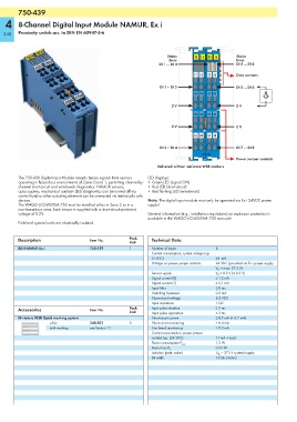
750-439
        750-439
   4    8-Channel Digital Input Module NAMUR, Ex i

  348   Proximity switch acc. to DIN EN 60947-5-6


                                                                    Status     13 14  15 16     Status
                                                                     Error                      Error
                                                                 DI 1 ... DI 4                  DI 5 ... DI 8
                                                                               E1 E2  E5  E6    Data contacts

                                                                 DI 1 + DI 2                    DI 5 ... DI 6
                                                                               0V 0V  0V  0V               A
                                                                                                           --
                                                                      0 V                       0 V
                                                                               0V 0V  0V  0V

                                                                      0 V                       0 V
                                                                               E3 E4  E7 E8

                                                                 DI 3 + DI 4                    DI 7 ... DI 8
                                                                                  750-439
                                                                                                Power jumper contacts
                                                                Delivered without miniature WSB markers

        The 750-439 Digital Input Module records binary signals from sensors   LED displays:
        operating in hazardous environments of Zones 0 and 1, permitting channel-by- • Green LED (signal ON)
        channel short-circuit and wire-break diagnostics. NAMUR sensors,   • Red LED (short-circuit)
        optocouplers, mechanical contacts (LED diagnostics can be turned off via   • Red flashing LED (wire-break)
        control byte) or other actuating elements can be connected via intrinsically safe
        devices.                                            Note: The digital input module must only be operated via Ex i 24VDC power
        The WAGO-I/O-SYSTEM 750 must be installed either in Zone 2 or in a   supply!
        non-hazardous area. Each sensor is supplied with a short-circuit-protected
        voltage of 8.2V.                                    General information (e.g., installation regulations) on explosion protection is
                                                            available in the WAGO-I/O-SYSTEM 750 manuals!
        Field and system levels are electrically isolated.


        Description                  Item No.        Pack.    Technical Data
                                                     Unit
        8DI NAMUR Ex i               750-439         1        Number of inputs         8
                                                              Current consumption, system voltage typ.
                                                              (5 VDC)                  56  mA
                                                              Voltage via power jumper contacts  24 VDC (provided via Ex i power supply
                                                                                       V O  = max. 27.3 V)
                                                              Sensor supply            V V  = 8.2 V (± 0.2 V)
                                                              Signal current (0)       ≤ 1.2 mA
                                                              Signal current (1)       ≥ 2.1 mA
                                                              Input filter             3.0 ms
                                                              Switching hysteresis     0.2 mA
                                                              Open-circuit voltage     8.2 VDC
                                                              Input resistance         1 kΩ
        Accessories                  Item No.        Pack.    Input pulse duration     ≥ 5 ms
                                                     Unit     Input pulse separation   ≥ 3 ms
        Miniature WSB Quick marking system                    Short-circuit current    ≤ 8.2 mA (± 0.2 mA)
                     plain           248-501         5        Short-circuit monitoring  > 6.4 mA
                     with marking    see Section 11           Line break monitoring    < 0.3 mA
                                                              Current consumption, power jumper
                                                              contact typ. (24 VDC)    11 mA + load
                                                                                       1.2 W
                                                              Power consumption P max.
                                                                                       0.54 W
                                                              Power loss P V
                                                              Isolation (peak value)   U M  = 375 V system/supply
                                                              Bit width                16 bits (status)