Page 346 - Wago_AutomationTechnology_Volume3_2015_US.pdf
P. 346

750-435
        750-435
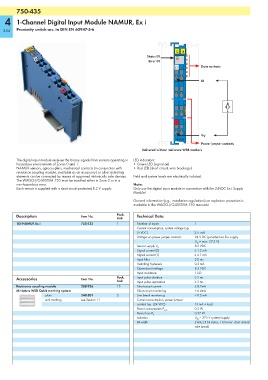
   4    1-Channel Digital Input Module NAMUR, Ex i

  344   Proximity switch acc. to DIN EN 60947-5-6


                                                                               13 14
                                                                  Status DI
                                                                   Error DI
                                                                                          Data contacts
                                                                               E1

                                                                                          DI


                                                                                                      A
                                                                                                      +

                                                                               +


                                                                                          V V
                                                                               750-435
                                                                                          Power jumper contacts
                                                                Delivered without miniature WSB markers

        The digital input module receives the binary signals from sensors operating in   LED indicators:
        hazardous environments of Zones 0 and 1.            • Green LED (signal on)
        NAMUR sensors, optocouplers, mechanical contacts (in conjunction with   • Red LED (short circuit, wire breakage)
        resistance coupling module, available as an accessory) or other actuating
        elements can be connected by means of approved intrinsically safe devices.  Field and system levels are electrically isolated.
        The WAGO-I/O-SYSTEM 750 must be installed either in Zone 2 or in a
        non-hazardous area.                                 Note:
        Each sensor is supplied with a short-circuit-protected 8.2 V supply.  Only use the digital input module in connection with the 24VDC Ex i Supply
                                                            Module!
                                                            General information (e.g., installation regulations) on explosion protection is
                                                            available in the WAGO-I/O-SYSTEM 750 manuals!

        Description                  Item No.        Pack.    Technical Data
                                                     Unit
        1DI NAMUR Ex i               750-435         1        Number of inputs         1
                                                              Current consumption, system voltage typ.
                                                              (5 VDC)                  2.5  mA
                                                              Voltage via power jumper contacts  24 V DC (provided via Ex-i supply
                                                                                       U O  = max. 27.3 V)
                                                                                       8.2 VDC
                                                              Sensor supply V V
                                                              Signal current (0)       ≤ 1.2 mA
                                                              Signal current (1)       ≥ 2.1 mA
                                                              Input filter             3.0 ms
                                                              Switching hysteresis     0.2 mA
                                                              Open-circuit voltage     8.2 VDC
                                                              Input resistance         1 kΩ
        Accessories                  Item No.        Pack.    Input pulse duration     ≥ 5 ms
                                                     Unit     Input pulse separation   ≥ 3 ms
        Resistance coupling module   288-936         15       Short-circuit current    ≤ 8.2mA
        Miniature WSB Quick marking system                    Short-circuit monitoring  > 6.4mA
                     plain           248-501         5        Line break monitoring    < 0.2 mA
                     with marking    see Section 11           Current consumption, power jumper
                                                              contact typ. (24 VDC)    13 mA + load
                                                                                       0.5 W
                                                              Power consumption P max.
                                                                                       0.37 W
                                                              Power loss P V
                                                              Isolation                U M  = 375 V system/supply
                                                              Bit width                2 bits; (1 bit status, 1 bit error: short circuit/
                                                                                       wire break)
   341   342   343   344   345   346   347   348   349   350   351