
Page 344 - Wago_AutomationTechnology_Volume3_2015_US.pdf
P. 344
750-606, 750-625/000-001
750-606,750-625/000-001
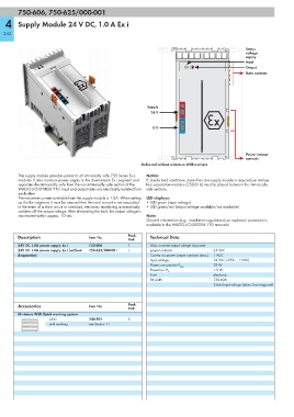
4 Supply Module 24 V DC, 1.0 A Ex i
342
Status
voltage
supply
Input
Output
Data contacts
Supply
24 V
0 V
4
Power jumper
contacts
Delivered without miniature WSB markers
This supply module provides power to all intrinsically safe 750 Series Ex i Notice:
modules. It also monitors power supply to the downstream Ex i segment and If, due to load conditions, more than one supply module is required per station,
separates the intrinsically safe from the non-intrinsically safe section of the four separation modules (750-616) must be placed between the intrinsically
WAGO-I/O-SYSTEM 750. Input and output sides are electrically isolated from safe sections.
each other.
The maximum current available from the supply module is 1.0A. When setting LED displays:
up the Ex-i segment, it must be ensured that this total current is not exceeded. • LED green (input voltage)
In the event of a short circuit or overload, electronic monitoring automatically • LED green/red (output voltage available/not available)
switches off the output voltage. After eliminating the fault, the output voltage is
reactivated within approx. 10 sec. Note:
General information (e.g., installation regulations) on explosion protection is
available in the WAGO-I/O-SYSTEM 750 manuals!
Description Item No. Pack. Technical Data
Unit
24V DC 1.0A power supply Ex i 750-606 1 Max. nominal output voltage via power
24V DC 1.0A power supply Ex i (without 750-625/000-001 1 jumper contacts 24 VDC
diagnostics) Current via power jumper contacts (max.) 1 ADC
Input voltage 24 VDC (-25% … +30%)
29 W
Power consumption P max.
< 5 W
Power loss P V
Fuse electronic
Bit width 750-606:
2 bits (input voltage failure, fuse triggered)
Accessories Item No. Pack.
Unit
Miniature WSB Quick marking system
plain 248-501 5
with marking see Section 11