
Page 339 - Wago_AutomationTechnology_Volume3_2015_US.pdf
P. 339
750-665/000-001
750-665/000-001
4-Channel Digital Input and Output Module PROFIsafe V1.3 4
337
13 14 15 16
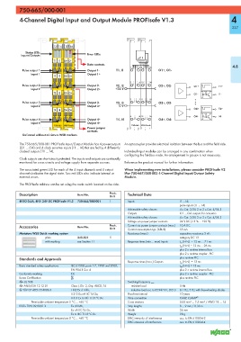
Status LEDs
Inputs/Outputs Error LEDs
T1 I1 O1+ O1-
Data contacts
9 13 4.8
Pulse output 1 Output 1- T1, I1 O1+, O1-
Input 1 Output 1+
T2 I2 O2+ O2-
10 14
Pulse output 2 Output 2- T2, I2 O2+, O2- O1+ T1+
Input 2 Output 2+ +24 V
T3 I3 O3+ O3-
O1- I1-
11 15
Pulse output 3 Output 3- T3, I3 O3+, O3-
Input 3 Output 3+ 0 V
O4+ T4+
T4 I4 O4+ O4-
12 16 O4- I4-
Pulse output 4 Output 4+ T4, I4 O4+, O4-
Input 4 Output 4+
750-665 PROFIsafe
Power jumper
contacts
Delivered without miniature WSB markers
The 750-665/000-001 PROFIsafe Input/Output Module has 4 power outputs An optocoupler provides electrical isolation between the bus and the field side.
(O1 ... O4) and 4 clock sensitive inputs (I1 ... I4) that are fed by 4 differently
clocked outputs (T1 ... T4). Individual input modules can be arranged in any combination when
configuring the fieldbus node. An arrangement in groups is not necessary.
Clock outputs are short-circuit protected. The inputs and outputs are continually
monitored for cross circuits and voltage supply from separate sources. Reference the product manual for further information.
The associated green LED for each of the 4 input channels and 4 output When implementing new installations, please consider PROFIsafe V2
channels indicates the signal state. Two red LEDs also indicate internal or iPar 750-667/000-003 4-Channel Digital Input/Output Safety
external errors. Module.
The PROFIsafe address can be set using the code switch located on the side.
Description Item No. Pack. Technical Data
Unit
4FDO 0.5A, 4FDI 24V DC PROFIsafe V1.3 750-665/000-001 1 Inputs I1 ... I4;
pulse inputs (T1 ... T4)
Achievable safety classes 4 x Cat. 2/SIL 2 or 2 x Cat. 4/SIL 3
Outputs O1 ... O4: outputs for actuators
Achievable safety classes 4 x Cat. 2/SIL 2 or 2 x Cat. 4/SIL 3
Voltage via power jumper contacts 24 V DC (-15 % ... +20 %)
Accessories Item No. Pack. Current via power jumper contacts (max.) 10 A DC
Unit
55 mA
Current consumption typ. (KBUS)
Miniature WSB Quick marking system Reactance (max.) capacitive reactance 2 nF;
plain 248-501 5 category DC 13
with marking see Section 11 Response times (min ... max) Inputs t on (H->L) = 13 ms ... 71 ms
t off (H->L) = 13 ms ... 26 ms
plus 2 x runtime internal bus
plus 2 x runtime coupler - PLC
Standards and Approvals plus runtime PLC
Response times (max.) Outputs t on (H->L) = 13 ms
Basic standard safety applications IEC 61508, parts 1-7, 1998 und 2000; t off (H->L) = 13 ms
EN 954-1 Cat. 4 plus 2 x runtime internal bus
Conformity marking 1 plus 2 x runtime coupler - PLC
Korea Certification plus runtime PLC
r UL 508 Swiching frequency max.
r ANSI/ISA 12.12.01 Class I, Div. 2, Grp. ABCD, T4 resistive load 5 Hz
4 TÜV 07 ATEX 554086 X I M2 Ex d I Mb, inductive load acc. to IEC947-5-1, DC13 0.1 Hz, 5 Hz with free-wheeling diodes
II 3 G Ex nA IIC T4 Gc, Proof test interval 10 years
II 3 D Ex tc IIIC T135°C Dc Wire connection CAGE CLAMP ®
Permissible ambient temperature 0 °C ... +60 °C Cross sections 0.08 mm² ... 2.5 mm² / AWG 28 ... 14
IECEx TUN 09.0001 X Ex d I Mb, Strip lengths 8 ... 9 mm / 0.33 in
Ex nA IIC T4 Gc, Width 24 mm
Ex tc IIIC T135°C Dc Weight 98 g
Permissible ambient temperature 0 °C ... +60 °C EMC immunity of interference acc. to EN 61000-6-2
EMC emission of interference acc. to EN 61000-6-4