
Page 337 - Wago_AutomationTechnology_Volume3_2015_US.pdf
P. 337
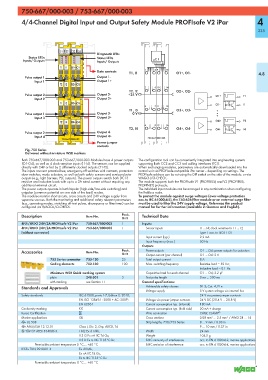
750-667/000-003 / 753-667/000-003
           750-667/000-003 / 753-667/000-003
           4/4-Channel Digital Input and Output Safety Module PROFIsafe V2 iPar                                    4

                                                                                                                    335


                            21 22  23 24
                                            Diagnostic LEDs
              Status LEDs                   Status LEDs
           Inputs/ Outputs                  Inputs/ Outputs
                            T1 I1  O1+ O1-
                                            Data contacts  T1, I1      9   13  O1+, O1-                             4.8
            Pulse output 1                  Output 1-
                Input 1                     Output 1+
                            T2 I2  O2+ O2-
                                                                       10  14
                                                          T2, I2               O2+, O2-
            Pulse output 2                  Output 2-     +24 V                                  O1+         T1
                Input 2                     Output 2+
                            T1 I3  O3+ O3-                                                       O1-         I1
                                                                       11  15
                                                          T1, I3               O3+, O3-
            Pulse output 1                  Output 3-       0 V
                Input 3                     Output 3+
                            T2 I4  O4+ O4-                                                       O4+         T2
                                                                       12  16
                                                          T2, I4               O4+, O4-          O4-         I4
            Pulse output 2                  Output 4-
                Input 4                     Output 4+              750-667/000-003
                            750-667/000-003
                                            Power jumper
                                            contacts
            Fig. 750 Series
            Delivered without miniature WSB markers
           Both 750-667/000-003 and 753-667/000-003 Modules have 4 power outputs   The configuration tool can be conveniently integrated into engineering systems
           (O1-O4), as well as 4 clock-sensitive inputs (I1-I4). The sensors can be supplied   supporting both CC2 and CC3 tool calling interfaces (TCI).
           directly with 24V or fed by 2 differently clocked outputs (T1-T2).  When exchanging modules, parameters are automatically downloaded into the
           The inputs connect potential-free, emergency-off switches with contacts, protection   control unit via PROFIsafe-compatible iPar server -- depending on settings. The
           door switches, mode selectors, as well as both safety sensors and semiconductor   PROFIsafe address can be set using the DIP switch on the side of the module, or via
           outputs (e.g., light barriers, PLC outputs). The power outputs switch both DC13   WAGO-I/O-CHECK.
           resistive and inductive loads with up to a 2A-rated current without requiring any   The module supports both the PROFIsafe V1 (PROFIBUS) and V2 (PROFIBUS,
           additional external circuit.                        PROFINET) protocols.
           The power outputs operate in both bipolar (high-side/low-side switching) and   The individual input modules can be arranged in any combination when configuring
           unipolar (common potential on one side of the load) modes.  the fieldbus node.
           The modules monitor short-circuits, cross circuits and 24V voltage supply from   To protect the module against surge voltages (over-voltage protection
           separate sources. Both the monitoring and additional safety relevant parameters   acc. to IEC 61000-4-5), the 750-626 filter module or an external surge filter
           (e.g., operating modes, switching off test pulses, discrepancy or filter times) can be   must be used to filter the 24V supply voltage. Reference the product
           configured via WAGO-I/O-CHECK.                      manual for further information (available in German and English).
           Description                 Item No.        Pack.    Technical Data
                                                       Unit
           4FDI/4FDO 24V/2A PROFIsafe V2 iPar  750-667/000-003  1  Inputs:
           4FDI/4FDO 24V/2A PROFIsafe V2 iPar   753-667/000-003  1  Sensor inputs         I1 ... I4; clock sensitive to T1 ... T2
           (without connector)                                                            Type 1 acc. to IEC61131
                                                                  Input current (typ.)    2.2 mA
                                                                  Input frequency (max.)  50 Hz
                                                                Outputs
           Accessories                 Item No.        Pack.      Power outputs           O1 ... O4; power outputs for actuators
                                                       Unit
                                                                  Output current (per channel)
                                                                                          O1 ... O4: 2 A
                       753 Series connector  753-120   25         Total output current    8 A
                       Coding elements  753-150        100        Max. switching frequency  Resistive load = 50 Hz;
                                                                                          Inductive load = 0.1 Hz
                       Miniature WSB Quick marking system         Capacitive load for each channel  O1 ... O4; 2.2 μF
                       plain           248-501         5          Test pulse length       0 ms ... 500 ms
                       with marking    see Section 11           General specifications:
           Standards and Approvals                                Achievable safety classes  SIL 3; Cat. 4, PL e
                                                                  Voltage supply          5 V system voltage via internal bus
           Safety standards         IEC 61508, parts 1-7, Edition 2: 2010;                24 V via power jumper contacts
                                    EN ISO 13849-1: 2008 + AC: 2009;   Voltage via power jumper contacts  24 V DC (20.4 V ... 28.8 V)
                                    EN 62061                      Current consumption typ. (internal)  180 mA
           Conformity marking       1                             Current consumption typ. (field side)  20 mA + charge
           Korea Certification                                    Wire connection         CAGE CLAMP ®
           Marine applications      GL                            Cross sections          0.08 mm² ... 2.5 mm² / AWG 28 ... 14
           r UL 508                                               Strip lengths, 750/753 Series  8 ... 9 mm / 0.33 in
           r ANSI/ISA 12.12.01      Class I, Div. 2, Grp. ABCD, T4                        9 ... 10 mm / 0.37 in
           4 TÜV 07 ATEX 554086 X   I M2 Ex d I Mb,               Width                   24 mm
                                    II 3 G Ex nA IIC T4 Gc,       Weight                  104.5 g
                                    II 3 D Ex tc IIIC T135°C Dc   EMC immunity of interference  acc. to EN 61000-6-2, marine applications
                 Permissible ambient temperature 0 °C ... +60 °C  EMC emission of interference  acc. to EN 61000-6-4, marine applications
           IECEx TUN 09.0001 X      Ex d I Mb,
                                    Ex nA IIC T4 Gc,
                                    Ex tc IIIC T135°C Dc
                 Permissible ambient temperature 0 °C ... +60 °C