Page 358 - Wago_AutomationTechnology_Volume3_2015_US.pdf
P. 358

750-485
        750-485
   4    2-Channel Analog Input Module 4-20 mA, Ex i

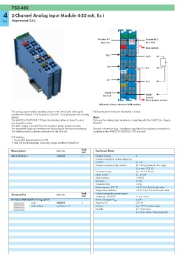
  356   Single-ended (S.E.)


                                                                              13 14  15 16
                                                                Function AI 1                 Function AI 2
                                                                  Error AI 1                  Error AI 2
                                                                              +  +
                                                                                              Data contacts

                                                                     V V  1
                                                                                              V V  2
                                                                              0V 0V
                                                                     0 V
                                                                                              0 V
                                                                              E1 E2

                                                                     AI 1
                                                                                              AI 2
                                                                              S  S

                                                                    Shield
                                                                   (screen)                   Shield
                                                                              750-485         (screen)
                                                                                              Power jumper contacts
                                                                Delivered without miniature WSB markers

        The analog input module provides power to the intrinsically safe signal   Field and system levels are electrically isolated.
        conditioners located in the hazardous Zone 0+1 and processes their analog
        signals.                                            Note:
        The WAGO-I/O-SYSTEM 750 must be installed either in Zone 2 or in a   Only use the analog input module in connection with the 24VDC Ex i Supply
        non-hazardous area.                                 Module!
        The 24 V supply is derived from the module's power jumper contacts.
        The transmitter supply is non-inherently electronically short-circuit-protected.  General information (e.g., installation regulations) on explosion protection is
        The shield (screen) is directly connected to the DIN rail.  available in the WAGO-I/O-SYSTEM 750 manuals!
        LED displays:
        • Green LED (signal current on/off)
        • Red LED (wire breakage, measuring range overflow/underflow)

        Description                  Item No.        Pack.    Technical Data
                                                     Unit
        2AI 4-20mA Ex i              750-485         1        Number of inputs         2
                                                              Current consumption, system voltage typ.
                                                              (5 VDC)                  31  mA
                                                              Voltage via power jumper contacts  24 V DC (provided via Ex-i supply
                                                                                       U O  = max. 27.3 V)
                                                              Transmitter supply       V V  = 16 V at 20 mA
                                                              Signal current           4 ... 20 mA
                                                              Input resistance         < 100 Ω
                                                              Resolution               12 bits
                                                              Conversion time          < 2 ms
                                                              Measuring error (25 °C)  < ± 0.2 % of the full scale value
                                                              Temperature coefficient  < ± 0.01 % / K of the full scale value
        Accessories                  Item No.        Pack.    Current consumption, power jumper
                                                     Unit     contact typ. (24 VDC)    11 mA + load
        Miniature WSB Quick marking system                    Power consumption P max.  1.3 W
                     plain           248-501         5        Power loss P V           0.75 W
                     with marking    see Section 11           Isolation                U M  = 375 V system/supply
                                                              Bit width                2 x 16 bits data
                                                                                       2 x 8 bits control / status (optional)
   353   354   355   356   357   358   359   360   361   362   363