
Page 362 - Wago_AutomationTechnology_Volume3_2015_US.pdf
P. 362
750-481/003-000
750-481/003-000
4 2-Channel Analog Input Module for Resistance Sensors, Ex i
360
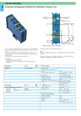
13 14 15 16
Function AI 1 Function AI 2
Error AI 1 Error AI 2
+R1 +R2 Data contacts
+R 1 2-conductor 3-conductor
+R 2
RL1 RL2
RL 1
RL 2
–R1 –R2 S S
-R 1
-R 2 Shield(screen)
750-481/003-000
Power jumper contacts
Delivered without miniature WSB markers
The analog input module allows the direct connection of Pt or Ni resistance Field and system levels are electrically isolated.
sensors and potentiometers located in hazardous environments of Zones 0
and 1. Note:
The WAGO-I/O-SYSTEM 750 must be installed either in Zone 2 or in a Only use the analog input module in connection with the 24VDC Ex i Supply
non-hazardous area. The 24V supply is derived from the module's power Module!
jumper contacts.
The shield (screen) is directly connected to the DIN rail. General information (e.g., installation regulations) on explosion protection is
available in the WAGO-I/O-SYSTEM 750 manuals!
LED indicators:
• Green LED (availability ON/OFF)
• Red LED ( short circuit, wire breakage, measuring range overflow/
underflow)
Description Item No. Pack. Technical Data
Unit
2AI RTD Ex i 750-481/003-000 1 Number of inputs 2
Current consumption, system voltage typ.
(5 VDC) 25 mA
Voltage via power jumper contacts 24 V DC (provided via Ex-i supply
U O = max. 27.3 V)
Conversion time 150 ... 500 ms (per channel)
Measuring error (25 °C) < ± 0.2 % of the full scale value
Temperature coefficient < ± 0.01 % / K of the full scale value
Measuring current (typ.) < 0.5 mA
Types of sensors (version setting made using WAGO-I/O-CHECK software)
RTD Pt100, Pt200, Pt500, Pt1000,
Ni100, Ni120, Ni1000
Accessories Item No. Pack. Resistors 1.2 kΩ, 5 kΩ
Unit Potentiometer setting 0 … 100 % (1.2 kΩ, 5 kΩ)
Miniature WSB Quick marking system Sensor connection 2-wire/3-wire
plain 248-501 5 Temperature range -200 °C ... + 850 °C (Pt);
with marking see Section 11 -60 °C ... +250 °C (Ni);
-80 °C ... +320 °C (Ni 120)
Resolution (over entire range) 0.1 °C, 0.1 Ω, 0.0049 %
Current consumption, power jumper
contact typ. (24 VDC) 12 mA
0.45 W
Power consumption P max.
0.45 W
Power loss P V
Isolation U M = 375 V system/supply
Bit width 2 x 16 bits data
2 x 8 bits control / status (optional)