
Page 366 - Wago_AutomationTechnology_Volume3_2015_US.pdf
P. 366
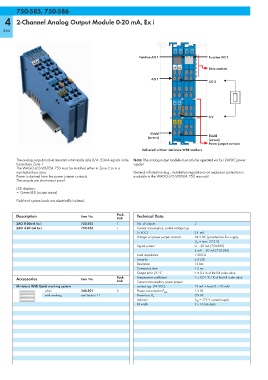
750-585,750-586
        750-585, 750-586
   4    2-Channel Analog Output Module 0-20 mA, Ex i

  364


                                                                              13 14  15  16
                                                               Function AO 1                  Function AO 2

                                                                              A1  A2          Data contacts


                                                                    AO 1
                                                                                              AO 2


                                                                              —  —


                                                                                              0 V
                                                                              S  S

                                                                    Shield
                                                                   (screen)                   Shield
                                                                              750-585         (screen)
                                                                                              Power jumper contacts
                                                                Delivered without miniature WSB markers

        The analog output module transmits intrinsically safe 0/4 - 20mA signals in the  Note: The analog output module must only be operated via Ex i 24VDC power
        hazardous Zone 1.                                   supply!
        The WAGO-I/O-SYSTEM 750 must be installed either in Zone 2 or in a
        non-hazardous area.                                 General information (e.g., installation regulations) on explosion protection is
        Power is derived from the power jumper contacts.    available in the WAGO-I/O-SYSTEM 750 manuals!
        The outputs are short-circuit proof.
        LED displays:
        • Green LED (output status)
        Field and system levels are electrically isolated.


        Description                  Item No.        Pack.    Technical Data
                                                     Unit
        2AO 0-20mA Ex i              750-585         1        No. of outputs           2
        2AO 4-20 mA Ex i             750-586         1        Current consumption, system voltage typ.
                                                              (5 VDC)                  21  mA
                                                              Voltage via power jumper contacts  24 V DC (provided via Ex-i supply
                                                                                       U O  = max. 27.3 V)
                                                              Signal current           0 ... 20 mA (750-585)
                                                                                       4 mA ... 20 mA (750-586)
                                                              Load impedance           < 500 Ω
                                                              Linearity                ± 2 LSB
                                                              Resolution               12 bits
                                                              Conversion time          < 2 ms
                                                              Output error 25 °C       < ± 0.2 % of the full scale value
        Accessories                  Item No.        Pack.    Temperature coefficient  < ± 0.01 % / K of the full scale value
                                                     Unit     Current consumption, power jumper
        Miniature WSB Quick marking system                    contact typ. (24 VDC)    19 mA + load (2 x 20 mA)
                     plain           248-501         5        Power consumption P max.  1.5 W
                     with marking    see Section 11           Power loss P V           0.9 W
                                                              Isolation                U M  = 375 V system/supply
                                                              Bit width                2 x 16 bits data