
Page 365 - Wago_AutomationTechnology_Volume3_2015_US.pdf
P. 365
4
363
9 13
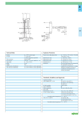
+TC 1 / +TC 2 +TC
10 14 A
270 pF MUX Logic
24 V D
ϑ VGL
Error 4.9
11 15
-TC 1 / -TC 2 -TC Function
0 V
270 pF
Common
(ground) 20 nF
12 16
Common Shield
(ground) (screen)
Shield
(screen)
Technical Data Explosion Protection
Isolation U M = 375 V system/supply Electric circuit, safety-relevant data V 0 = 14.4 V; I 0 = 29.1 mA; P 0 = 52.4 mW;
Bit width 2 x 16 bits data Characteristic: Linear
2 x 8 bits control/status (optional) Reactances Ex ia IIC L 0 = 52 mH; C 0 = 650 nF
Wire connection CAGE CLAMP ® Reactances Ex ia IIB L 0 = 100 mH; C 0 = 4.0 μF
Cross sections 0.08 mm² ... 2.5 mm² / AWG 28 ... 14 Reactance Ex ia IIA L 0 = 300 mH; C 0 = 15.8 μF
Strip lengths 8 ... 9 mm / 0.33 in Reactances Ex ia I L 0 = 400 mH; C 0 = 17.9 μF
Width 24 mm Reactances (The above-listed ratings do not account for
Weight 48 g the coincidental occurrence of
EMC immunity of interference acc. to EN 61000-6-2, marine applications capacitances and inductances. For ratings
EMC emission of interference acc. to EN 61000-6-3, marine applications taking the coincidental occurrence of
capacitances and inductances into
account, see manual)
Standards, Guidelines and Approvals
Conformity marking 1
ATEX Guideline 94 / 9 / EC EN 60079-0, EN 60079-11,
EN 60079-15, EN 60079-26,
EN 60079-31
EC EMC guideline 2004/108/EC
Korea Certification
Marine applications BV, GL, LR, NKK, PRS, RINA
r UL 508
r ANSI/ISA 12.12.01 Class I, Div. 2, Grp. ABCD, T4
4 TÜV 12 ATEX 106032 X I M2 (M1) Ex d [ia Ma] I Mb,
II 3 (1) G Ex nA [ia Ga] IIC T4 Gc,
II 3 (1) D Ex tc [ia Da] IIIC T135°C Dc
Permissible ambient temperature 0 °C ... +60 °C
IECEx TUN 12.0039 X Ex d [ia Ma] I Mb,
Ex nA [ia Ga] IIC T4 Gc,
Ex tc [ia Da] IIIC T135°C Dc
Permissible ambient temperature 0 °C ... +60 °C