
Page 368 - Wago_AutomationTechnology_Volume3_2015_US.pdf
P. 368
750-633
750-633
4 Up/Down Counter, Ex i
366
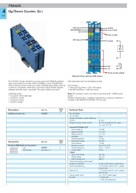
13 14 15 16
U/D (Gate) CLOCK
Error U/D (Gate) Error CLOCK
DO
U/D CLK Data contacts
U/D (Gate)
CLOCK
A
-
0 V 0 V
A1 0 V
DO
0 V
750-633
Power jumper contacts
Delivered without miniature WSB markers
The 750-633 Counter records binary pulse signals with NAMUR-compliant Field and system levels are electrically isolated.
levels and transmits the counter state to the fieldbus system. The U/D input
allows either Up or Down counting. Counter and digital output (DO) can be set LED indicators:
or reset via control byte. A limit value can be set at which the DO output is • Green LED (Up/Down + CLK + DO status)
activated when this value is exceeded. The output is short-circuit proof. • Red LED (Up/Down + CLK error status)
Operating modes: Note: The up/down counter must only be operated via Ex i 24VDC power
• Up counter with enable input supply!
•Up/Down counter General information (e.g., installation regulations) on explosion protection is
• Frequency counter available in the WAGO-I/O-SYSTEM 750 manuals!
• Peak-time counter
Description Item No. Pack. Technical Data
Unit
Up/Down Counter, Ex i 750-633 1 No. of counters 1
No. of outputs 1
Current consumption, system voltage typ.
(5 VDC) 25 mA
Voltage via power jumper contacts 24 V DC (provided via Ex-i supply
U O = max. 27.3 V)
Counter U/D (Gate), CLK
8.2 VDC
Sensor supply V V
Signal current (0) ≤ 1.2 mA
Signal current (1) ≥ 2.1 mA
Input filter 10 μs
Switching hysteresis 0.2 mA
Accessories Item No. Pack. Open-circuit voltage 8.2 VDC
Unit Input resistance 1 kOhm
Miniature WSB Quick marking system Short-circuit current 8.2 mA (+/- 5 %)
plain 248-501 5 Switching frequency 20 Hz ... 50 kHz
with marking see Section 11 Counter depth 32 bits
Output:
Open-circuit voltage 24 V DC
Output voltage 24 V DC
285 Ω
Internal resistance R i
Current consumption, power jumper
contact typ. (24 VDC) 31 mA + sensor load + actuator load
2.2 W (sensor load: 8.2 mA + actuator
Power consumption P max.
load: 45 mA)
1.7 W (sensor load: 8.2 mA + actuator
Power loss P V
load: 45 mA)
Isolation (peak value) U M = 375 V system/supply
Bit width 1 x 32-bit data,
1 x 8-bit status/diagnostics