
Page 364 - Wago_AutomationTechnology_Volume3_2015_US.pdf
P. 364
750-487/003-000
750-487/003-000
4 2-Channel Analog Input Module for Thermocouples Ex i
362
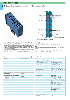
13 14 15 16
Function AI 1 Function AI 2
ErrorAI 1 ErrorAI 2
+TC +TC Data contacts
+TC 1
+TC 2
-TC -TC
-TC 1
-TC 2
M M S S
Common Shield
(ground) (screen)
750-487/003-000
Power jumper contacts
Delivered without miniature WSB markers
The analog input module directly connects two thermocouples operating in LED displays:
hazardous environments of Zones 0 and 1. • Green LED (availability ON/OFF)
The WAGO-I/O-SYSTEM 750 must be installed either in Zone 2 or in a • Red LED (wire breakage, measuring range overflow/underflow)
non-hazardous area. Internal electrical isolation allows operation of grounded
sensors. The module automatically linearizes the entire temperature range. Note:
Cold junction compensation mitigates the clamping unit offset voltage over the Only use the analog input module in connection with the 24VDC Ex i Supply
0°C - 55°C operating range. Module!
The 24 V supply is derived from the module's power jumper contacts. Field and
system levels are electrically isolated. General information (e.g., installation regulations) on explosion protection is
The module mode is parameterized via WAGO-I/O-CHECK 3 software. available in the WAGO-I/O-SYSTEM 750 manuals!
Description Item No. Pack. Technical Data
Unit
2AI TC Ex i 750-487/003-000 1 Number of inputs 2
Current consumption, system voltage typ.
(5 VDC) 13.5 mA
Voltage via power jumper contacts 24 V DC (provided via Ex-i supply
U O = max. 27.3 V)
Conversion time ≤ 320 ms (both channels)
Measuring error (25 °C) < ± 6 K (type K);
voltage input < ± 2 K;
cold juncrtion compensation < ± 4 K
Temperature coefficient < ± 0.2 K / K of full scale value (type K)
Cold junction compensation internal; at each pair of modules
Resolution (over entire range) 0.1°C or 0.01 mV for voltage
Accessories Item No. Pack. measurement
Unit Internal resistance ≥ 1MΩ
Miniature WSB Quick marking system Measuring range Thermocouple:
plain 248-501 5 Type B: +600°C ... +1,800°C
with marking see Section 11 Type E: –100°C ... +1,000°C
Type J: –100°C… +1,200°C
Type K: –100°C ... +1,370°C* *(default
setting)
Type L: -100°C ... +900°C
Type N: –100°C … +1,300°C
Type R: 0°C … +1,700°C
Type S: –50°C ... +1,700°C
Type T: –100°C ... +400°C
Type U: -25°C ... +600°C
voltage sensor:
MB1: ± 30 mV
MB2: ± 60 mV
MB3: ± 120 mV
0.3 W
Power consumption P max.
0.3 W
Power loss P V