
Page 360 - Wago_AutomationTechnology_Volume3_2015_US.pdf
P. 360
750-484
750-484
4 2-Channel Analog Input Module 4-20 mA HART, Ex i
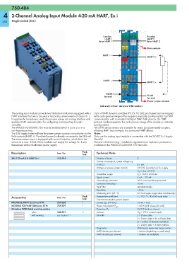
358 Single-ended (S.E.)
Function 13 14 15 16 Function
HART 1 HART 2
Error HART 1 Error HART 2
E1 E2 Data contacts
HART 1 +
HART 2 +
+ +
HART1 –
HART 2 –
S S
Shield
(screen) Shield
750-484 (screen)
Power jumper contacts
Delivered without miniature WSB markers
The analog input module connects two field-side transformers equipped with a Up to 4 HART dynamic variables (PV, SV, TV, QV) per channel can be mapped
HART interface that are to be used in hazardous environments of Zones 0+1. in the cyclic process image of the coupler or controller (configurable). For HART
It supplies the transducers, reads the process values via analog interface and communication with connected intelligent HART field devices, the HART
enables HART communication for configuring and importing dynamic protocol can be mapped in the cyclic process image of the coupler or controller
variables. (configurable).
The WAGO-I/O-SYSTEM 750 must be installed either in Zone 2 or in a FDT/DTM device drivers are available for select (programmable) couplers,
non-hazardous area. allowing HART tool routing to the connected HART device.
The 24V supply is derived from the power jumper contacts via multipliers to the Note:
field contacts (HART +). The shield (screen) is directly connected to the DIN rail. Only use the analog input module in connection with the 24VDC Ex i Supply
The measurement input is equipped with current limitation, which limits the Module!
current to a max. 25mA. These modules can supply the voltage for 2-wire General information (e.g., installation regulations) on explosion protection is
transducers without dedicated power supply. available in the WAGO-I/O-SYSTEM 750 manuals!
Description Item No. Pack. Technical Data
Unit
2AI 4-20 mA S.E. HART Ex i 750-484 1 Number of inputs 2
Current consumption, system voltage typ.
(5 VDC) 25 mA
Voltage via power jumper contacts 24 V DC (provided via Ex-i supply
U O = max. 27.3 V)
Transmitter supply V V = 16.5 V at 20 mA
Signal current 4 mA ... 20 mA
Overvoltage protection 30 V, reverse polarity protected
Conversion time (typ.) 10 ms
Input filter parameterizable
Resolution 12 bits
Measuring error (25 °C) 0.2 % of upper range value (non-linearity)
Accessories Item No. Pack. Temperature coefficient < ± 0.01 % / K of full scale value
Unit Current consumption, power jumper
PROFIBUS/HART Gateway DTM 759-360 1 contact typ. (24 VDC) 26 mA + load
MODBUS TCP/HART-Gateway DTM 759-359 1 Power consumption P max. 1.60 W (with slaves (20 mA))
Miniature WSB Quick marking system Power loss P V 0.62 W (without slaves)
plain 248-501 5 Isolation U M = 375 V system/supply
with marking see Section 11 Bit width 2 x 2 bytes data
2 x 2 bytes data + 2n x 4 bytes data
(n = number of dynamic variables)
2 x 2 bytes data + 6 bytes mailbox
Diagnostics Wire break, measuring range overrun
HART devices per channel 1 device (single-drop, no multi-drop)
HART modems per channel 1 modem (no multiplex)