
Page 356 - Wago_AutomationTechnology_Volume3_2015_US.pdf
P. 356
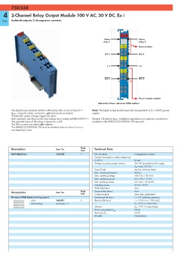
750-538
        750-538
   4    2-Channel Relay Output Module 100 V AC, 30 V DC, Ex i

  354   Isolated outputs; 2 changeover contacts


                                                                               13 14
                                                                    Status                Status
                                                                   relay 1                relay 2
                                                                               14 24      Data contacts

                                                                     DO 1                 DO 2
                                                                               11 21

                                                                      L 1                 L 2
                                                                               12 22
                                                                    _____                 _____
                                                                     DO 1                 DO 2


                                                                               750-538
                                                                                          Power jumper contact
                                                                Delivered without miniature WSB markers

        The digital output module switches intrinsically safe circuits of Zone 0+1   Note: The digital output module must only be operated via Ex i 24VDC power
        (e.g., magnetic valves, contactors, optical/acoustic encoders).  supply!
        The internal system voltage triggers the relay.
        Both maximum switching current and voltage must comply with EN 60079-11.  General information (e.g., installation regulations) on explosion protection is
        The switched status of the relays is shown by a LED.  available in the WAGO-I/O-SYSTEM 750 manuals!
        The NO contacts are electrically isolated.
        The WAGO-I/O-SYSTEM 750 must be installed either in Zone 2 or in a
        non-hazardous area.


        Description                  Item No.        Pack.    Technical Data
                                                     Unit
        2DO RELAY Ex i               750-538         1        No. of outputs           2 changeover contacts
                                                              Current consumption, system voltage typ.
                                                              (5 VDC)                  26 mA
                                                              Voltage via power jumper contacts  24 V DC (provided via Ex-i supply
                                                                                       U O  = max. 27.3 V)
                                                              Type of load             resistive, inductive, lamps
                                                              Max. switching frequency  20/min
                                                              Max. switching voltage   100 V AC / 30 V DC
                                                              Max. switching current   0.5 A AC / 1 A DC
                                                              Min. switching current   0.01 mA / 10 mV DC
                                                              Switching power          50 VA / 30 W
                                                              Pull-in time (max.)      4 ms
        Accessories                  Item No.        Pack.    Drop-out time (max.)     4 ms
                                                     Unit     Contact material         Silver alloy, gold-plated
                                                                                           8
        Miniature WSB Quick marking system                    Mechanical life (min.)   1 x 10  switching operations
                                                                                           5
                     plain           248-501         5        Electrical life (min.)   1 x 10  (0.5 A / 100 V AC)
                                                                                           5
                     with marking    see Section 11                                    2 x 10  (1 A / 30 V DC)
                                                              Isolation                V M  = 375 V system/supply
                                                                                       0.8 W
                                                              Power consumption P max.
                                                                                       0.8 W
                                                              Power loss P V
                                                              Bit width                2 bits (status)