
Page 434 - Wago_AutomationTechnology_Volume3_2015_US.pdf
P. 434
6 I/O-System — SPEEDWAY
432 Interfaces and Configurations
(1) Module marking WMB
A 1) 2) (2) System bus connection M12 B 2) a)
3) (3) Sensor/actuator marking 1)
a) (4) Supply connections M12 3)
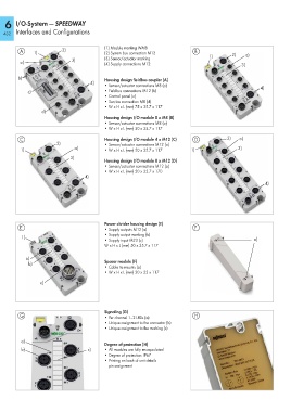
b) Housing design fieldbus coupler (A)
4)
• Sensor/actuator connections M8 (a) 4)
c) • Fieldbus connections M12 (b)
• Control panel (c)
• Service connection M8 (d)
• W x H x L (mm) 75 x 35.7 x 117
d)
Housing design I/O module 8 x M8 (B)
• Sensor/actuator connections M8 (a)
• W x H x L (mm) 50 x 35.7 x 117
C Housing design I/O module 4 x M12 (C) D 2) a)
2) • Sensor/actuator connections M12 (a)
1) a) • W x H x L (mm) 50 x 35.7 x 117 1) 3)
3)
Housing design I/O module 8 x M12 (D)
• Sensor/actuator connections M12 (a)
• W x H x L (mm) 50 x 35.7 x 170
4)
4)
Power divider housing design (E)
E • Supply outputs M12 (a) F
• Supply output marking (b)
1) a)
• Supply input M23 (c)
W x H x L (mm) 50 x 35.7 x 117
a)
b) Spacer module (F)
• Cable tie mounts (a)
• W x H x L (mm) 20 x 25 x 117
c)
Signaling (G)
G • Per channel 1–2 LEDs (a) H
• Unique assignment to the connector (b)
• Unique assignment to the marking (c)
a)
Degree of protection (H)
b) c) • All modules are fully encapsulated
• Degree of protection: IP67
• Printing on back of unit details
pin assignment