
Page 436 - Wago_AutomationTechnology_Volume3_2015_US.pdf
P. 436
6 I/O-System — SPEEDWAY
434 Application and Installation Instructions
Power supply
The modular structure permits both individual 756-120x/..., ETHERNET Cable
supply of I/O modules and aggregation to ETHERNET RJ-45 Connector 756-130x/..., System Bus Cable
supply groups (e.g., for implementing emergency Power Divider 767-9101 750-975
stop groups). Thus, each supply group and each PWR DVI 756-9409/0060-0000 System Terminating Plug
individual supply can be operated using different X 6 767-0111 767-0111 767-0111
power supplies at the same potential. Two supply X 5 Spacer Spacer Spacer
X
lines are routed within the supply lines (gray). U X 4 Fieldbus Coupler I/O Module I/O Module I/O Module
LS 3
for logic and sensor supply is always electrically X ETHERNET FC 8DI 4AI RTD 4AO U/I 8DO 2A
2 SBM
isolated from U for the actuator supply. X 1 1 FB 2
A
MS 1 CS X X
7 8 Ch4 Ch4 7 8
24 V NS 2 PS
X 7 U LS U A ACT/LNK X 7 6 X X X 7 6
You can connect additional I/O modules until 767-9101 12I RES 5 X 6 X Ch3 Er4 4 X Ch3 Er4 4 5 X 6
11I B/E
9I SN 8I 27 X 4 3 3 X 4
the highest permissible current load of 4 A for 7I 26 6I 25 5I 24 4I 23 5 3 X 4 Er3 Ch2 X Er3 Ch2 X 5 3 X 4
one supply line (U and/or U ) is reached. To 3I 22 2I 21 1I 20 X 3 2 X X Ch1 Er2 2 X Ch1 Er2 2 X 3 2 X
LS A 1 2 1 1 1 2
connect other SPEEDWAY modules, you have to X 1 0 Er1 Er1 X 1 0
24 V
24 V
24 V
24 V
reconnect the power supply. An exception are the 756-9604/0060-0000 M23 Connector COM 767-1301 767-6402 767-7401 767-4803
U LS U A
U LS U A
U LS U A
U LS U A
2 A output modules which cannot route the po-
wer supply due to an increased power demand.
Supply 24 V DC
By using a power divider, it is possible to distri-
bute the U and U power supplies over six M12
LS A 756-310x/..., Power Supply Cable
connectors. The combination of point-to-point
power distribution and linear power distribution/
routing offers the greatest flexibility to optimize
the supply lines for the respective application and
to supply power over large distances.
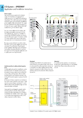
Attention! Attention!
Interference-free WAGO I/O modules have no For interference-free operation, it is necessary to
active influence on the safety function, they are not lay the power cables separately or to use shielded
Interference-free in safety-related applica- an active part of the safety application and are not supplied lines. Please observe the notes in the
tions a substitute for the safety switching device! When manual!
To safely and easily perform cost-effective, centra- using the components in safety functions, the corre-
lized deactivation of complete actuator groups, sponding notes must be observed in the correspond-
the actuator’s power supply can be switched off ing manual.
using a safety switching device. This can either
be performed for each individual actuator or by
turning off the power supply to a group of control
outputs. Safety switch module/ Output module
In the event of failure, ensure that no interference Safety module
from other current or power circuits occurs — even
when the control voltage is switched off — so the Safe
defined safety function properties (logic and time output
response) remain unchanged. 24 V U A Actuator 1
0 V U
Some modules are designed to provide interfe- A
rence-free safety functionality. These modules
comply with safety requirements up to Category Safety
4 of DIN EN ISO 13849-1:2007. Safety catego- components Actuator 2
ry and performance level depend solely on the
Safe
safety components and their wiring. input
Logic
Safe
input
Safe
output
Example: Two-pin shutdown of the power supply of all digital outputs