
Page 12 - Shroeder - Filter Systems
P. 12
Technical Cleanliness and
Contamination Management Basics
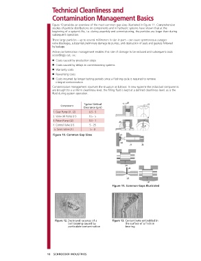
Figure 10 provides an overview of the most common gap sizes illustrated in Figure 11. Comprehensive
studies of particle distributions on components and in hydraulic systems have shown that at the
beginning of a system’s life, i.e. during assembly and commissioning, the particles are larger than during
subsequent operation.
These large particles – up to several millimeters in size in part – can cause spontaneous outages:
valve blockages, substantial preliminary damage to pumps, and destruction of seals and gaskets followed
by leakage.
Active contamination management enables this rate of damage to be reduced and subsequent costs
accordingly cut, i.e.:
■ Costs caused by production stops
■ Costs caused by delays in commissioning systems
■ Warranty costs
■ Reworking costs
■ Costs incurred by longer testing periods since a flushing cycle is required to remove
integral contamination
Contamination management counters the situation as follows: In new systems the individual components
are brought to a uniform cleanliness level, the filling fluid is kept at a defined cleanliness level, as is the
fluid during system operation.
Typical Critical
Component
Clearance (µm)
1. Gear Pump (J1, J2) 0.5 - 5
2. Vane-cell Pump (J1) 0.5 - 5
3. Piston Pump (J2) 0.5 - 1
4. Control Valve (J1) 5 - 25
5. Servo Valve (J1) 5 - 8
Figure 10. Common Gap Sizes
Figure 11. Common Gaps Illustrated
Figure 12. Destroyed raceway of a Figure 13. Contaminate embedded in
ball bearing caused by the surface of a friction
particulate contamination bearing
10 SCHROEDER INDUSTRIES