
Page 17 - Shroeder - Filter Systems
P. 17
Fluid Condition Field Analysis Tools
A representative sample is taken of the fluid and analyzed as follows: Procedure
1. Manual procedure according to ISO 4407 (Hydraulic fluid power – Fluid contamination – in Evaluating
Determination of particulate contamination by the counting method using a microscope).
Fluid Samples
ISO 4407 contains a description of a microscopic counting method for membranes. 100 ml of the sample According to
undergoing analysis is filtered through an analysis membrane featuring an average pore size of < 1 µm ISO 4406:1999,
and square markings. NAS 1638 and
The standard also describes the cleaning procedure and maximum particle count of the negative control. SAE AS 4059
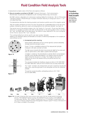
After the analysis membranes are dried, 10, 20 or 50 squares are counted depending on the size of the
particles, followed by adding the values and extrapolating to the membrane diameter. See figure 16.
The manual count of the particles is done in the “old” levels of > 5 µm and > 15 µm since the longest
dimension of a particle is counted in ISO 4407 yet the diameter of the area-equivalent circle is counted in
the “new” ISO 4406:1999. As described above, the reference values obtained for this count correspond
to the reference values of the “new” evaluation.
This counting method can only be used for very clean samples. Generally
speaking, the cleanliness classes are estimated on the basis of reference photographs or the samples are
automatically counted.
2. Automated particle counting
Below follows a description of how common particle counters employing
the light extinction principle function.
Figure 17 shows a simplified rendering of the measurement principle
employed in the light extinction principle.
The light source transmits the light (monochromatic light for the most part)
onto an optical sensor, which emits a specific electrical signal.
Figure 16. A shadow is created on the photodiode if a particle (black) comes between
the light source and the photodetector. This shadow causes the electric
signal emitted by the sensor to change. This change can be used to
determine the size of the shadow cast by this particle and thus the
particle size.
This procedure enables the cleanliness classes according to ISO 4406:1987,
ISO 4406:1999, NAS 1638 and SAE AS 4059 to be accurately determined.
The “noise” involved in this measurement principle is extraneous liquids and
gases which cause the light beam to be interrupted and thus be counted as
particles.
The particle counter should be calibrated according to ISO 11943
(for ISO 4406:1999).
Figure 17.
TCM TPM TIM TMU FS AMFS CTU
Figure 18. Schroeder Industries offers seven products (see Figure 18) that include particle monitoring
®
®
®
services: TPM TestMate Particle Counter, TIM TestMate In-Line Counter, TCM TestMate
®
®
Contamination Monitor, TMU TestMate Monitoring Unit, CTU TestMate Contamination Test
®
®
Unit, the FS Filtration Station and Asset Management Filtration System . Product information for
all of these is included in this catalog.
SCHROEDER INDUSTRIES 15