Page 22 - Shroeder - Filter Systems
P. 22

Analyzing the Data


                      Results    The contamination monitoring results describe the condition at the time the sampling is done.
                                 The findings might look like this:
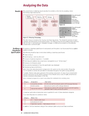
                                                                                                     Micro-photograph
                                                                                                    analysis
                                                                                                    membrane
                                                                                                    Particulate
                                                                                                    contamination
                                                                                                    of a component
                                                                                                    prior to storage
                                                              5 mg         9 mg    Figure 22.
                                                                          300 um
                                                                                                    Micro-photograph
                                                                                                    analysis
                                                                                                    membrane
                                                                                                    Particulate
                                                                                                    contamination of
                                                                                                    a component
                                                                                                    after being in
                                                                                                    storage
                                 Figure 21. Housing Processing                     Figure 23.       for 2 weeks

                                 This chart shows an excerpt of the housing manufacturing process. The component samples are taken
                                 upstream and downstream of the washing station. The findings show that the washing station performs
                                 well and that it is well positioned. Subsequent storage is not being done properly as the particulate
                                 contamination is almost double.


                   Drafting a    By applying a cleanliness specification to components and the system it can be ensured that as-supplied
                  Cleanliness    quality is constant.
                Specification    The following should be kept in mind when drafting a cleanliness specification:
                                 ■ State of the art
                                 ■ Benchmarking – what do others do?
                                 ■ Inclusion of previous experience – if available
                                 ■ Defining and implementing contamination management as an “official project”
                                 ■ Inclusion of all hierarchy levels
                                 ■ Accurate documentation of how the specification was developed
                                 ■ Developing clear-cut definitions
                                 Next, it has to be determined which components in the system are the most sensitive. Frequently,
                                 it is not possible to achieve the same level of cleanliness throughout the system during assembly.
                                 If suitable, filtration takes place upstream of the sensitive components. An area of low-contamination-
                                 sensitive components can be defined upstream of this filtration and an area of highly contamination-
                                 sensitive components downstream of the filter.
                                 These individual components or system areas should be subdivided into sensitivity areas.

                                  Category  Designation        Description
                                    A       Low particle-sensitivity  For the most part low-pressure systems with large gap tolerances
                                    B       Particle-sensitive  Low-pressure systems with small gap tolerances
                                                                 High-pressure systems with small gap tolerances and with exacting
                                    C       High particle sensitivity
                                                               demands made of safety and security systems
                                 A maximum particulate contamination value is specified for each of these cleanliness categories.
                                 A car motor illustrates this subdivision below:

                                   Category  Motor Area
                                     A        Air  /  Coolant water circuit
                                     B      Low-pressure oil circuit
                                     C        Diesel direct injection  /  High-pressure oil circuit
                                 In addition, the fluid cleanliness ratings of the individual system and process fluids are defined.


                              20  SCHROEDER INDUSTRIES
   17   18   19   20   21   22   23   24   25   26   27